Debris resistant bearing system and method

a bearing system and anti-corrosion technology, applied in the direction of fluid tightness measurement, wheel attachments, instruments, etc., can solve the problems of pipeline defects, corrosion, cracks, etc., and achieve the effect of reducing pressure and a larger area

Active Publication Date: 2012-07-10
PURETECH VENTURES
View PDF16 Cites 2 Cited by
  • Summary
  • Abstract
  • Description
  • Claims
  • Application Information

AI Technical Summary

Benefits of technology

[0013]That is, a plunger may be free to translate within an axle. Accordingly, the plunger may move until it reaches an equilibrium position at which the axial force urging it in one direction is equal to the axial force urging it in an opposite direction. With pressure being equal to force divided by area, when the ax

Problems solved by technology

Once installed, a pipeline will inevitably corrode or otherwise degrade.
Typical defects of a pipeline may include corrosion, gouges, dents, cracks, and the like.
Corrosion may cause pitting, general wall loss, or cracking, thereby lowering the maximum operating pressure of the pipeline.
Without detection and preemptive action, all such defects and vulnerabilities may lead to pipeline failure.
While collecting such information, an in-line inspection tool is exposed to th

Method used


Image

  • Debris resistant bearing system and method
  • Debris resistant bearing system and method
  • Debris resistant bearing system and method

Examples


Embodiment Construction

[0019]It will be readily understood that the components of the present invention, as generally described and illustrated in the drawings herein, could be arranged and designed in a wide variety of different configurations. Thus, the following more detailed description of the embodiments of the system and method of the present invention, as represented in the drawings, is not intended to limit the scope of the invention as claimed, but is merely representative of various embodiments of the invention. The illustrated embodiments of the invention will be best understood by reference to the drawings, wherein like parts are designated by like numerals throughout.

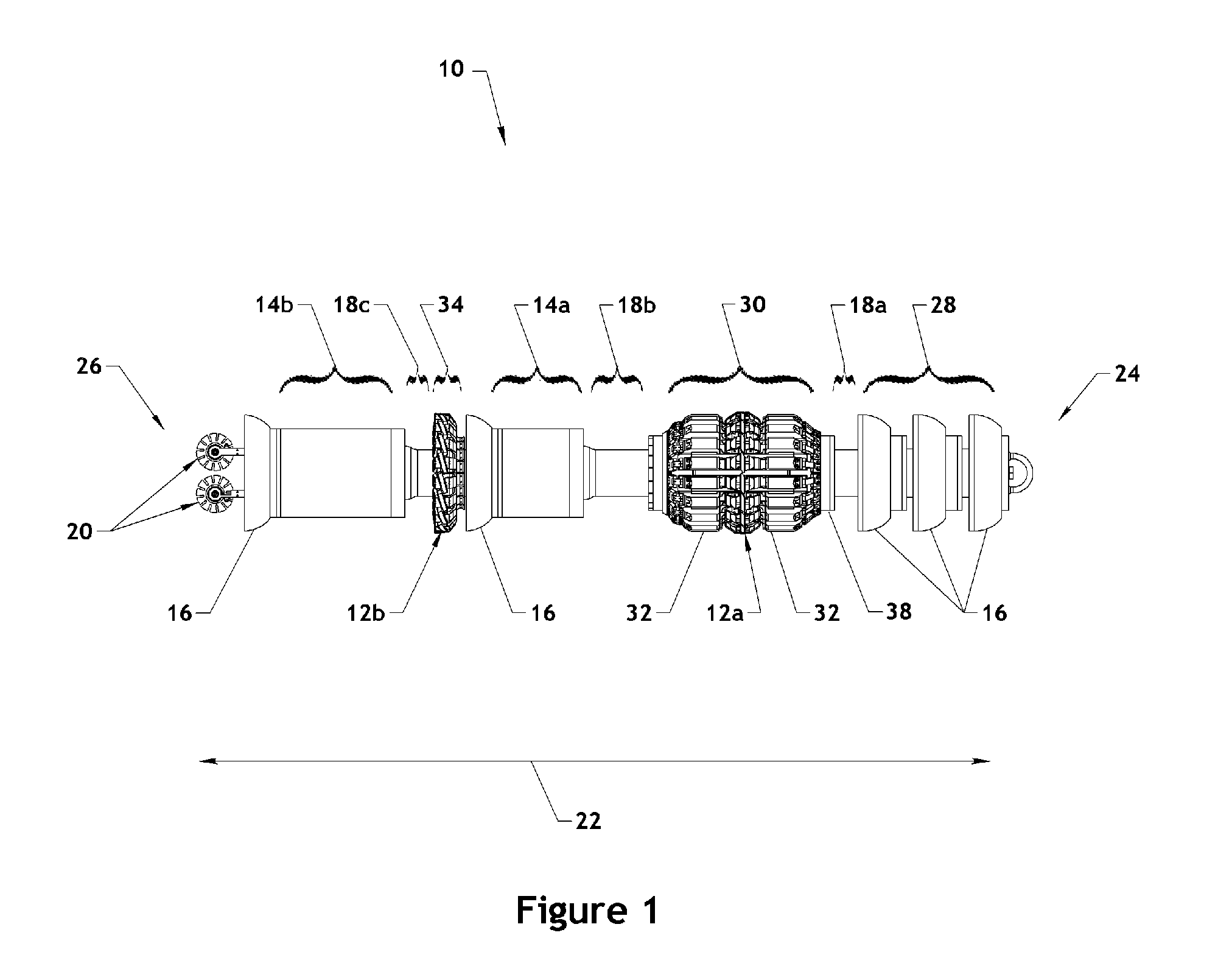
[0020]Referring to FIG. 1, an in-line inspection tool 10 or vehicle 10 in accordance with the present invention may comprise various components including one or more inspection assemblies 12, canisters 14, driving cups 16, couplers 18, position sensors 20, and the like. Depending on the configuration of the in-line inspection too...


PUM


Abstract

A system and method are disclosed for protecting bearings operating in dirty environments. The system may include a reservoir of lubricant, a bearing, and a regulator. The bearing may border on both the dirty environment and the reservoir. Accordingly, the bearing may be exposed to the solid particles carried by the fluid within the environment, as well as the lubricant of the reservoir. The regulator may ensure that the pressure within the reservoir is greater than the pressure of the dirty environment. Due to the higher pressure within the reservoir, the bearing may be preferentially filled with lubricant rather than dirty fluid from the environment.

Description

BACKGROUND[0001]1. Field of the Invention[0002]This invention relates to bearing systems for use in dirty environments and, more particularly, to apparatus and methods for bearing systems suitable for use on a pipeline inspection tool.[0003]2. Background of the Invention[0004]Oil, petroleum products, natural gas, hazardous liquids, water, and the like are often transported using pipelines. The majority of these pipelines are constructed from steel pipe. Once installed, a pipeline will inevitably corrode or otherwise degrade. Proper pipeline management requires identification, monitoring, and repair of defects and vulnerabilities of the pipeline. For example, information collected about the condition of a pipeline may be used to determine safe operating pressures, facilitate repair, schedule replacement, and the like.[0005]Typical defects of a pipeline may include corrosion, gouges, dents, cracks, and the like. Corrosion may cause pitting, general wall loss, or cracking, thereby lowe...

Claims


Application Information

Patent Timeline
IPC IPC(8): F16C19/00G01M3/08
CPCF16C33/664F16C33/6677F16L55/48B60B15/00B60B2360/10F16C2370/00F16C2361/00F16C19/06F16C19/54F16L2101/30F16C2326/02
Inventor HOYT, PHILIP M.
Owner PURETECH VENTURES
Why Eureka
Try Eureka