Turbine vane with high temperature capable skins

a technology of turbine engines and skins, applied in the direction of machines/engines, stators, liquid fuel engines, etc., can solve the problems of vane detracting, overheating and burning up, and complex active cooling systems

Inactive Publication Date: 2012-07-10
SIEMENS ENERGY INC
View PDF60 Cites 18 Cited by
  • Summary
  • Abstract
  • Description
  • Claims
  • Application Information

AI Technical Summary

Problems solved by technology

However, even with a thermal barrier coating, the turbine vane still requires active cooling to prevent it from overheating and burning up.
Such active cooling involves systems are usually complicated and costly.
Further, the use of air to cool the vane detracts from the use of such air for other beneficial purposes in the engine.
In many engine designs, demands to improve engine performance have been met in part by increasing engine firing temperatures, thereby further challenging the material capabilities of the vanes and further increasing cooling requirements.

Method used


Image

  • Turbine vane with high temperature capable skins
  • Turbine vane with high temperature capable skins
  • Turbine vane with high temperature capable skins

Examples


Embodiment Construction

[0023]Embodiments of the invention are directed to a turbine vane assembly that can accommodate the use of high temperature capable materials. Embodiments of the invention are shown in FIGS. 1-10, but the present invention is not limited to the illustrated structure or application.

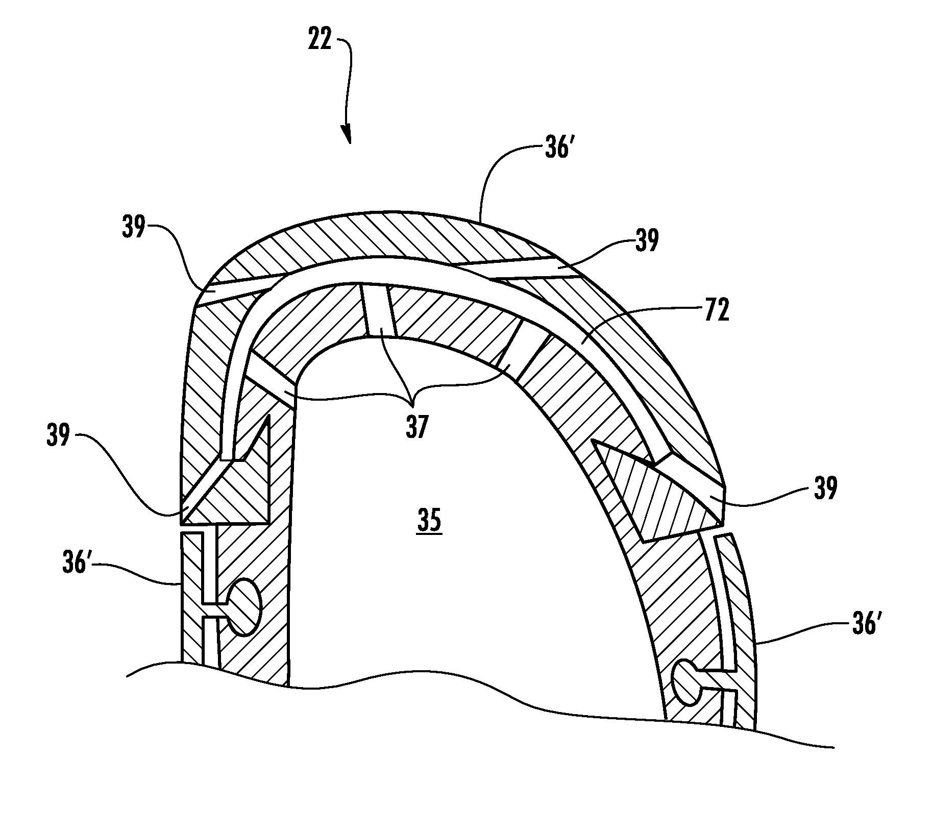
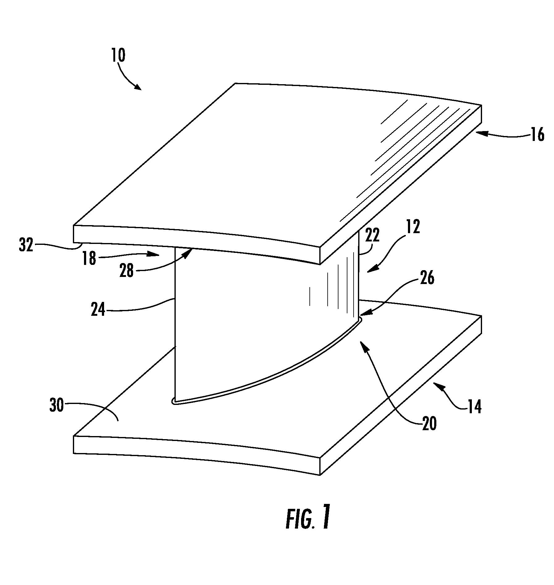
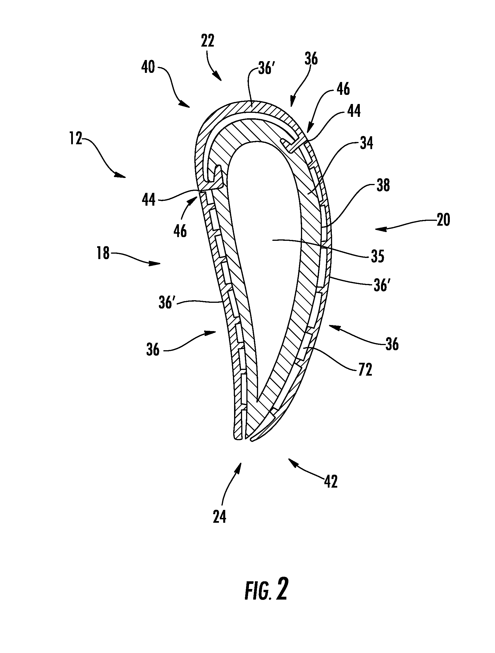
[0024]FIG. 1 shows a turbine vane 10 according to aspects of the invention. As shown, the turbine vane 10 includes an airfoil 12, an inner shroud 14 and an outer shroud 16. The airfoil 12 has a pressure side 18 and a suction side 20. Further, the airfoil 12 has a leading edge 22 and a trailing edge 24. The airfoil 12 can have an inner end region 26 and an outer end region 28. The terms “inner” and “outer,” as used herein, are intended to mean relative to the axis of the turbine when the vane 10 is installed in its operational position. The inner shroud 14 can have a gas path face 30, which is directly exposed to the turbine gas flow path. Similarly, the outer shroud 16 can have a gas path face 32, which is...


PUM

PropertyMeasurementUnit
thicknessaaaaaaaaaa
refractoryaaaaaaaaaa
temperatureaaaaaaaaaa

Abstract

A turbine vane assembly includes an airfoil extending between an inner shroud and an outer shroud. The airfoil can include a substructure having an outer peripheral surface. At least a portion of the outer peripheral surface is covered by an external skin. The external skin can be made of a high temperature capable material, such as oxide dispersion strengthened alloys, intermetallic alloys, ceramic matrix composites or refractory alloys. The external skin can be formed, and the airfoil can be subsequently bi-cast around or onto the skin. The skin and the substructure can be attached by a plurality of attachment members extending between the skin and the substructure. The skin can be spaced from the outer peripheral surface of the substructure such that a cavity is formed therebetween. Coolant can be supplied to the cavity. Skins can also be applied to the gas path faces of the inner and outer shrouds.

Description

STATEMENT REGARDING FEDERALLY SPONSORED DEVELOPMENT[0001]Development for this invention was supported in part by Contract No. DE-FC26-05NT42646 awarded by the United States Department of Energy. Accordingly, the United States Government may have certain rights in this invention.FIELD OF THE INVENTION[0002]Aspects of the invention relate in general to turbine engines and, more particularly, to turbine vanes in the turbine section of a turbine engine.BACKGROUND OF THE INVENTION[0003]During the operation of a turbine engine operation, high temperature, high velocity gases flow through alternating rows of stationary vanes and rotating blades in the turbine section. Turbine vanes must be cooled in order to withstand the high temperature environment. Turbine vanes have been coated with thermal barrier coatings to minimize the amount of cooling required. However, even with a thermal barrier coating, the turbine vane still requires active cooling to prevent it from overheating and burning u...

Claims


Application Information

Patent Timeline
Patent Type & Authority Patents(United States)
IPC IPC(8): F01D5/14F03D11/00F04D29/38
CPCB22D19/04F01D9/041F01D25/12Y10T29/49332F05D2260/20F05D2300/603F05D2230/21
Inventor MORRISON, JAY A.
Owner SIEMENS ENERGY INC
Why Eureka
Try Eureka