

Methods and systems for assisted direct start control
a technology of assisted direct start and start control, which is applied in the direction of engine starters, machines/engines, etc., can solve the problems of increasing the time required to recharge the accumulator and launch the vehicle, accelerating pump wear and tear, and reducing fuel savings. , to achieve the effect of reducing exhaust emissions, fuel saving, and reducing nois
- Summary
- Abstract
- Description
- Claims
- Application Information
AI Technical Summary
Benefits of technology
Problems solved by technology
Method used
Image

Examples
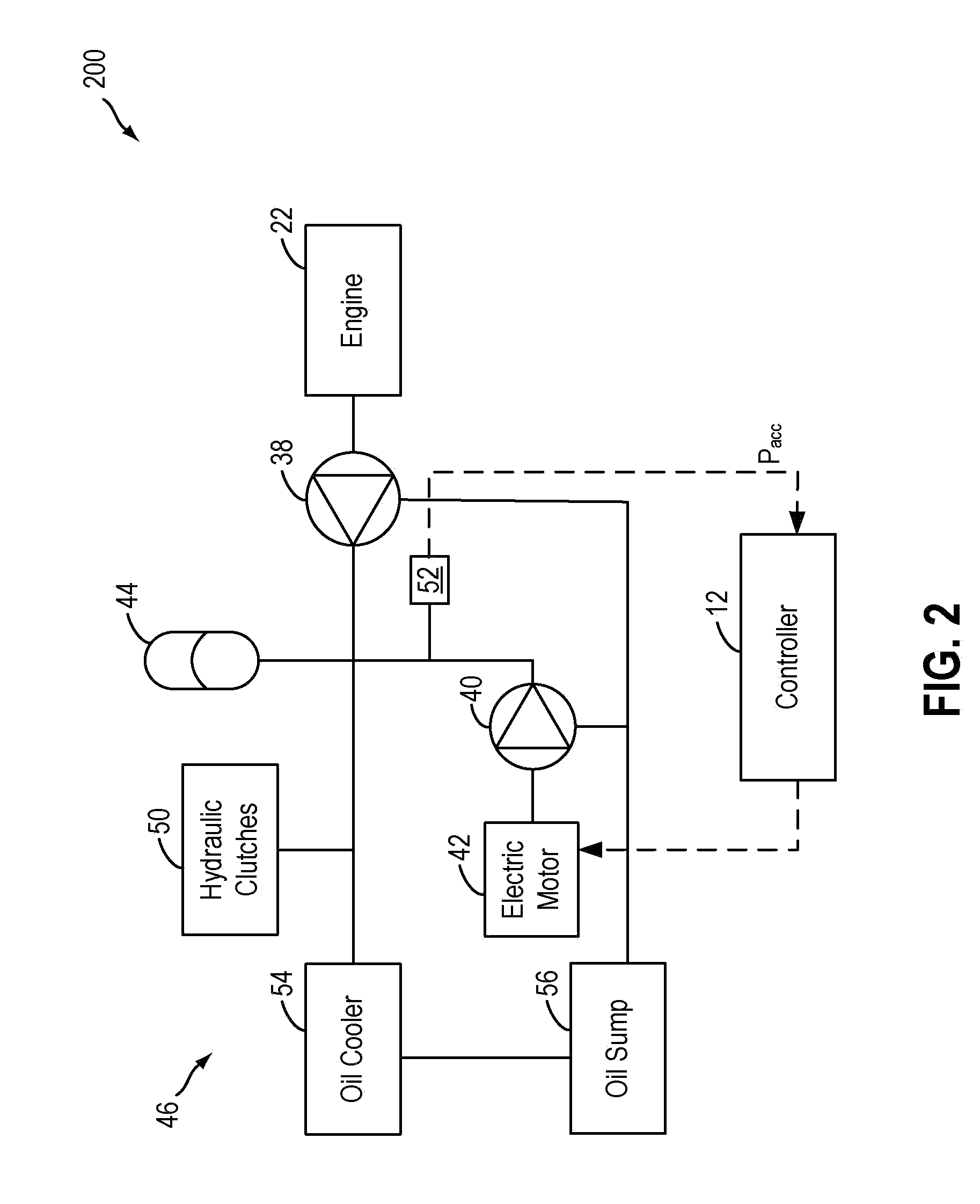
embodiment 200
[0024]FIG. 2 shows a simplified embodiment 200 of the hydraulic circuit 46 of FIG. 1. FIGS. 3-5 then depict detailed alternate embodiments of the hydraulic circuit of FIG. 2. It will be appreciated that components introduced in FIG. 2 may be similarly numbered in FIGS. 3-5, and may not be reintroduced for reasons of brevity.
[0025]Returning to FIG. 2, hydraulic circuit 46 includes mechanical oil pump 38, operated in concert with engine 22, and auxiliary electric oil pump 40, operated by electric motor 42. Pumps 38 and 40 may pump transmission fluid from oil sump 56 and deliver pressurized fluid into hydraulic circuit 46. Oil sump 56 provides the fluid reservoir to the electric pump 40 and the engine driven mechanical pump 38.
[0026]The pressurized fluid may be delivered to one or more hydraulically actuated transmission components, or hydraulic clutches 50. Accordingly, one or more of the hydraulic clutches 50 may be maintained in a stroked, partially engaged or fully engaged state. B...
embodiment 300
[0030]FIG. 3 shows a first detailed embodiment 300 of the hydraulic circuit 46 of FIG. 2. Herein, check valve 39 is coupled to the outlet of mechanical oil pump 38 to prevent backflow there-through. Similarly, check valve 41 is coupled to the outlet of auxiliary electric oil pump 40 to prevent backflow there-through. Pressure sensor 52 is positioned substantially between check valves 39 and 41 to provide an estimate of the accumulator pressure (Pacc) to controller 12.
[0031]Flow of transmission fluid through the one or more hydraulically actuated transmission components, or hydraulic clutches 50, may be controlled by respective hydraulic clutch control valves 51. As such, even when closed, some amount of fluid may leak through the hydraulic clutch control valves 51 and accordingly any pressure difference caused by the leakage may need to be compensated by the accumulator 44 and / or the electric oil pump 40.
[0032]Flow of transmission fluid through oil cooler 54 may be controlled by oil...
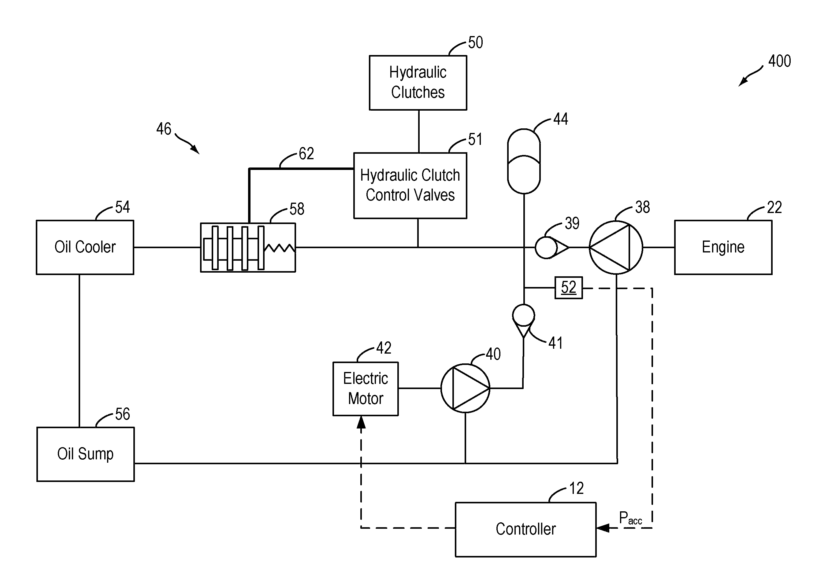
embodiment 400
[0035]FIG. 4 shows a second detailed embodiment 400 of the hydraulic circuit 46 of FIG. 2. Herein, a valve closure line 62 may be included to enable an assisted closure of the oil cooler flow control valve 58. Specifically, valve closure line 62 may connect oil cooler flow control valve 58 with hydraulic clutch control valves 51. Herein, closing the oil cooler flow control valve includes adjusting (e.g., opening, or closing, depending on the valve configuration) the hydraulic clutch control valve 51 to generate hydraulic pressure in valve closure line 62, the generated hydraulic pressure enabling closure of the oil cooler flow control valve 58. Specifically, during an engine shutdown, controller 12 may command a hydraulic clutch control valve 51 corresponding to a hydraulic clutch 50 that is not immediately involved in an engine restart, such as a reverse gear clutch control valve associated with a reverse gear clutch, to pressurize a land in the oil cooler flow control valve 58 by ...
PUM
 Abstract
Description
Claims
Application Information