Ultrasonic vibration system and method for removing/avoiding unwanted build-up on structures

a vibration system and ultrasonic technology, applied in the direction of generator/motor, transportation and packaging, cleaning using liquids, etc., can solve the problems of reducing handling, component failure, and component performance decline, so as to avoid overheating or improve the overall area of coverage, improve performance, and avoid the effect of overheating

Inactive Publication Date: 2012-07-10
FBS INC
View PDF10 Cites 29 Cited by
  • Summary
  • Abstract
  • Description
  • Claims
  • Application Information

AI Technical Summary

Benefits of technology

[0009]It is an objective of an aspect of the invention to provide a method and arrangement for removing or preventing the formation of ice, mud, or other debris or contaminants, from structures where such capability would be beneficial.
[0010]It is also an objective of an aspect of the invention to reduce the amount of power required for ice, mud, debris or contamination removal or prevention via appropriate ultrasonic actuator design to excite specific ultrasonic modes in the structure.
[0011]It is a further objective of an aspect of the invention to improve the overall area of coverage for prevention of contamination and decontamination activities by using frequency tuning, over some frequency range and at some frequency increment, to change the structural areas where maximum ultrasonic stresses occur when considering the ultrasonic stresses produced in the structure from one or more actuators.

Problems solved by technology

Ice formation on structures and components can cause decreases in component performance and, in some cases, component failure.
Ice formation on helicopter rotor blades or on the wing leading edges of fixed-wing aircraft, for example, alter the aerodynamic characteristics of the aircraft and can result in reduced handling.
Icing conditions, for the case of aircraft, often result in flight cancellations or delays.
In the event that icing conditions are encountered during flight, ice build-up, which reduces aircraft handling and maneuverability, can cause the aircraft to crash.
These systems require significant power levels for operation.
For the case of rotorcraft, the high power levels required by the thermal systems result in compromised rotorcraft functionality.
Further, the thermal deicing systems often melt ice which then refreezes on other parts of the blade, wing, or component.
The build up of dirt, mud, frozen soil, or other debris on structures can cause reduced functionality and increased weight.
For example, excavation equipment can be difficult to start and operate if debris accumulates on the undercarriage of the equipment of vehicle.
For excavation equipment, debris formation is sometimes mitigated by debris-phobic coatings which do not always work well and can wear overtime.
Using this time-consuming approach, project delays are often caused.
Another example where debris build-up causes unwanted downtimes and increased cleaning costs is in the food industry where bacteria or other films can accrete to the inner diameter surface of tubing or pipes used to transport product.

Method used


Image

  • Ultrasonic vibration system and method for removing/avoiding unwanted build-up on structures
  • Ultrasonic vibration system and method for removing/avoiding unwanted build-up on structures
  • Ultrasonic vibration system and method for removing/avoiding unwanted build-up on structures

Examples


Embodiment Construction

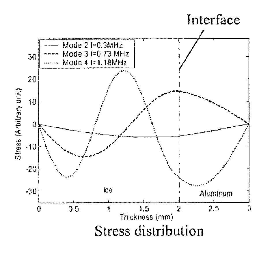
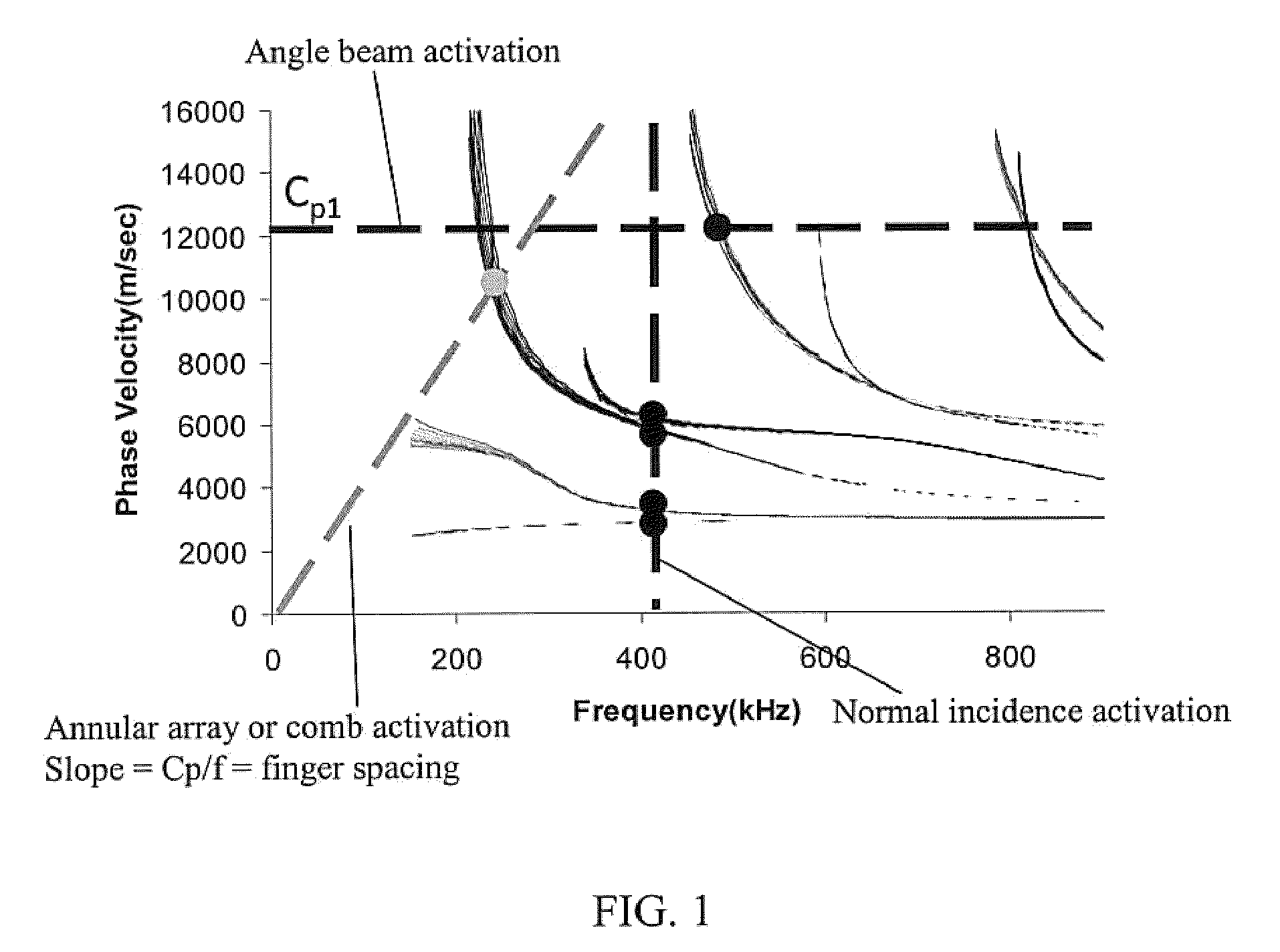
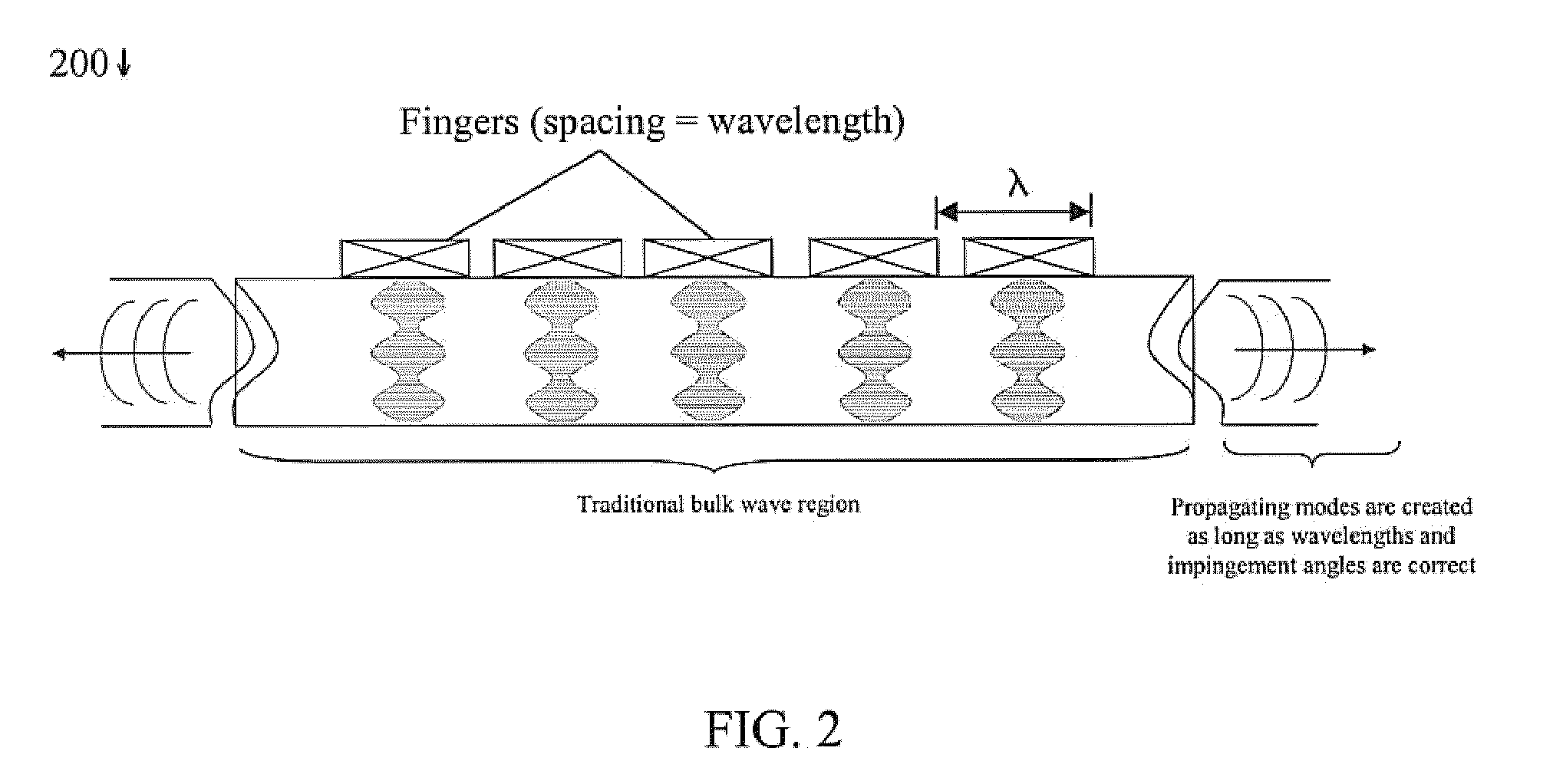
[0028]In one non-limiting method of the invention, a phase velocity dispersion curve space is developed for a structure, in this example called a host structure. The host structure can be an airplane wing, a boat, a structural steel skeleton of a building, or other. The phase velocity dispersion curve space is then evaluated with respect to either a longitudinal wave (“Lamb type wave”) or shear horizontal wave case for the structure such that activation produces a Lamb type wave or shear horizontal wave in the structure by using a specific actuator design. The appropriate point chosen on the velocity dispersion curve space is based on the wave structure across the thickness of the substrate / ice or substrate / contaminant structure. Maximum or reasonable shear stress or normal stress is generated at that point chosen on the velocity dispersion curve space in order to fracture, delaminate, or weaken the interface between ice or materials adhering to the host structure substrate. An angl...


PUM


Abstract

An ultrasonic method for removing and / or avoiding unwanted build-up on structures is provided, wherein the term build-up refers to, but is not limited to, ice, dirt, mud, or other wanted debris or contamination. Deicing or anti-icing structures of interest can include, but are not limited to, helicopter rotor blades, other helicopter blade components, fixed wing aircraft components, windshields in aircraft, automobiles, and other vehicles, ship hulls or other ship components, heat exchangers and other tubing where frost or ice could form, air-conditioning components, head lamp and other light coverings, bridge structures and components, and any structure where anti-icing or deicing would be beneficial. One or more ultrasonic actuators permanently embedded or coupled to the structure may be used accomplish the removal. The technique presented herein could also be utilized for non-destructive evaluation and structural health monitoring applications.

Description

CROSS-REFERENCE TO RELATED APPLICATIONS[0001]This application seeks priority under 35 U.S.C. §119(e) to U.S. Provisional Patent Application 61 / 056,681, filed May 28, 2008, the entirety of which is incorporated by reference.FIELD OF THE INVENTION[0002]Aspects of the invention relate to deicing, anti-icing, de-contamination, or contamination prevention for structures where such capability would be beneficial. The technique invented here could also be utilized in non-destructive testing and structural health monitoring applications.BACKGROUND INFORMATION[0003]Ice formation on structures and components can cause decreases in component performance and, in some cases, component failure. Ice formation on helicopter rotor blades or on the wing leading edges of fixed-wing aircraft, for example, alter the aerodynamic characteristics of the aircraft and can result in reduced handling. Icing conditions, for the case of aircraft, often result in flight cancellations or delays. In the event that ...

Claims


Application Information

Patent Timeline
Patent Type & Authority Patents(United States)
IPC IPC(8): H01L41/09B64D15/20B64D15/00
CPCB64D15/00
Inventor ROYER, JR., ROGER L.ROSE, JOSEPH L.SMITH, EDWARD C.PALACIOS, JOSE L.
Owner FBS INC
Why Eureka
Try Eureka