Programmable metallization cell structure including an integrated diode, device including the structure, and method of forming same

a metallization cell, integrated diode technology, applied in semiconductor devices, digital storage, instruments, etc., can solve the problems of high cost of manufacture, large energy consumption for data storage, and particularly volatile dynamic ram (“dram”), and achieve the effect of facilitating rapid growth of a conductive region

Inactive Publication Date: 2012-07-10
AXON TECH
View PDF14 Cites 29 Cited by
  • Summary
  • Abstract
  • Description
  • Claims
  • Application Information

AI Technical Summary

Benefits of technology

[0011]The ways in which the present invention addresses various drawbacks of now-known programmable devices are discussed in greater detail below. However, in general, the present invention provides a programmable structure that is relatively easy and inexpensive to manufacture, which is relatively easy to program, and which can be variably programmed.
[0015]In accordance with another embodiment of the invention, a lateral programmable structure is formed by forming an ion conductor layer overlying a substrate and forming two or more electrode structures in contact with the ion conductor layer. In accordance with one aspect of this embodiment, the structure includes a conductive layer adjacent the ion conductor to facilitate rapid growth of a conductive region within or on the ion conductor.
[0016]In accordance with another embodiment of the invention, a programmable device may be formed on a surface of a substrate. In accordance with one aspect of this embodiment, the substrate includes a microelectronic circuit. In accordance with a further aspect of this embodiment, the programmable device is formed overlying the microelectronic circuit and conductive lines between the microelectronic circuit and the programmable device are formed using conductive wiring schemes within the substrate and the memory device. This configuration allows transmission of more bits of information per bus line.
[0021]In accordance with additional embodiment of the invention, the structures include an additional conductive layer proximate one or more of the electrodes to improve the speed of the read / write process.

Problems solved by technology

Dynamic RAM (“DRAM”) is particularly volatile in that it must be “refreshed” (i.e., recharged) every few microseconds in order to maintain the stored data.
Static RAM (“SRAM”) will hold the data after one writing so long as the power source is maintained; once the power source is disconnected, however, the data is lost.
In general, these RAM devices can take up significant chip area and therefore may be expensive to manufacture and consume relatively large amounts of energy for data storage.
Other storage devices such as magnetic storage devices (e.g., hard disks and magnetic tape) as well as other systems, such as optical disks, CD-RW and DVD-RW are non-volatile, have extremely high capacity, and can be rewritten many times. Unfortunately, these memory devices are physically large, are shock / vibration-sensitive, require expensive mechanical drives, and may consume relatively large amounts of power.
These negative aspects make such memory devices non-ideal for low power portable applications such as lap-top and palm-top computers, personal digital assistants (“PDAs”), and the like.
Once programmed, the WORM device cannot be reprogrammed.
Thus, such devices are generally not well suited for use in portable electronic devices.
EEPROM devices are generally easier to program, but suffer from other deficiencies.
In particular, EEPROM devices are relatively complex, are relatively difficult to manufacture, and are relatively large.
Consequently, EEPROM cost per bit of memory capacity is extremely high compared with other means of data storage.
Another disadvantage of EEPROM devices is that, although they can retain data without having the power source connected, they require relatively large amounts of power to program.
This power drain can be considerable in a compact portable system powered by a battery.
Since the memory structures of the FPGA devices are generally based on other technologies, the FPGA devices often exhibit similar advantages and disadvantages of the underlying memory technology.

Method used


Image

  • Programmable metallization cell structure including an integrated diode, device including the structure, and method of forming same
  • Programmable metallization cell structure including an integrated diode, device including the structure, and method of forming same
  • Programmable metallization cell structure including an integrated diode, device including the structure, and method of forming same

Examples


Embodiment Construction

[0039]The present invention generally relates to programmable microelectronic structures, to devices and arrays including the structures, and to methods of forming the structures, devices, and arrays.

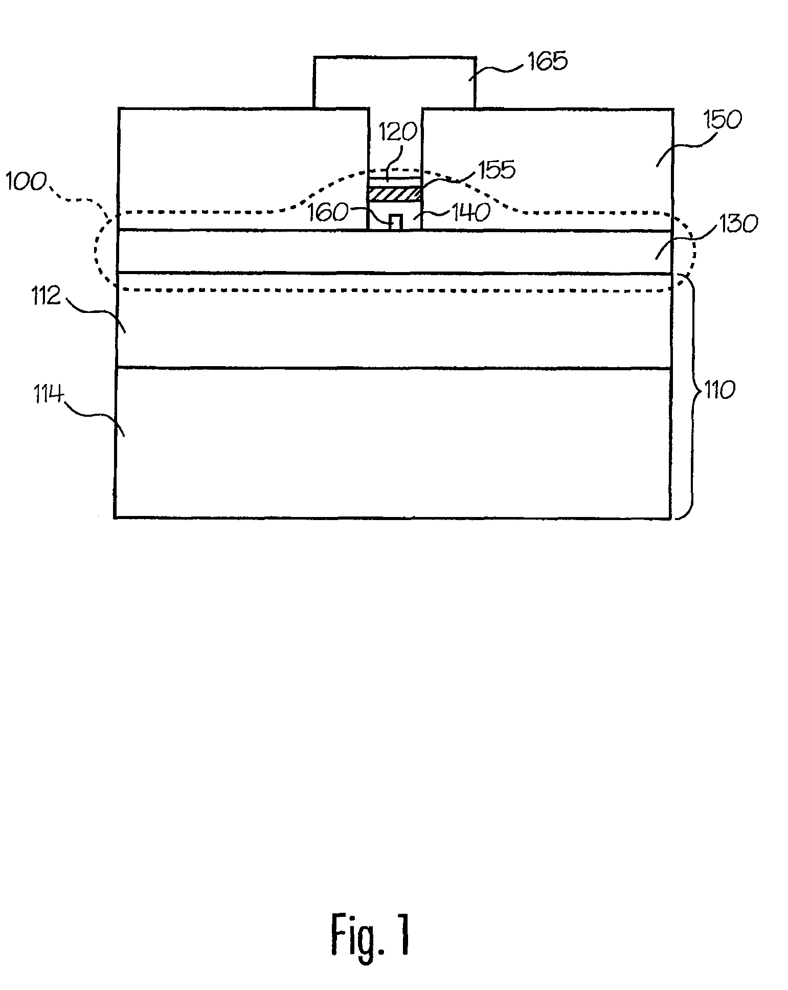
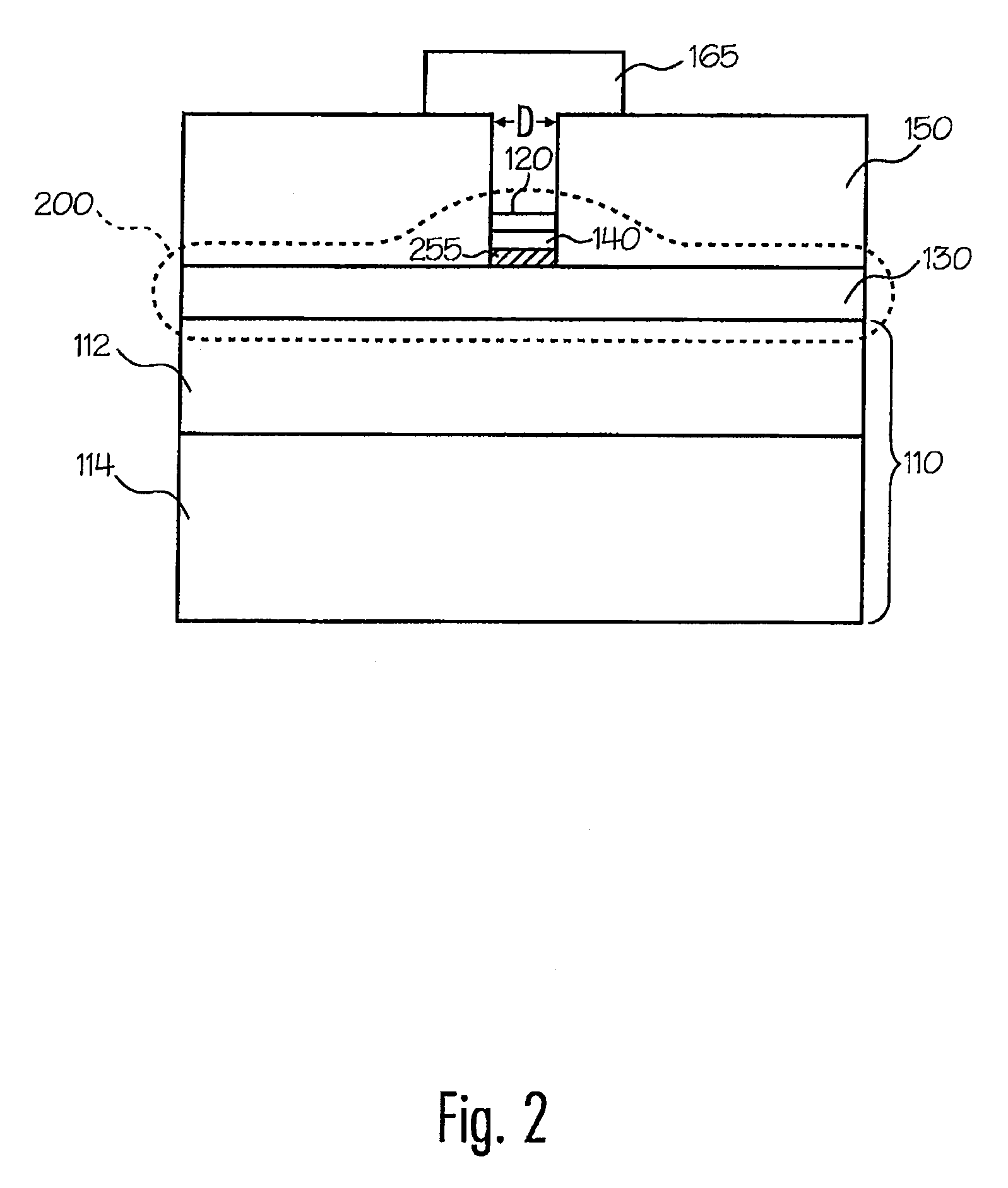
[0040]FIGS. 1 and 2 illustrate programmable microelectronic structures 100 and 200 formed on a surface of a substrate 110 in accordance with an exemplary embodiment of the present invention. Structures 100 and 200 include electrodes 120 and 130, an ion conductor 140, and optionally include buffer or barrier layers or regions 155 and / or 255.

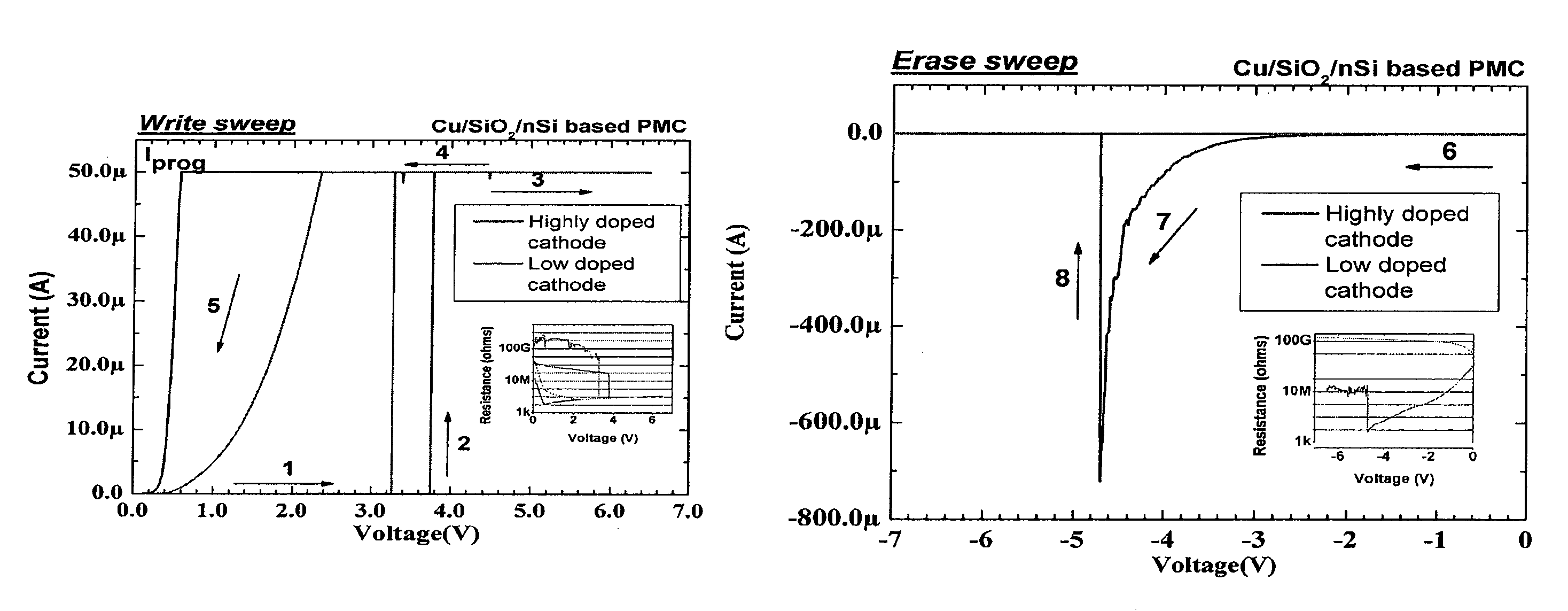
[0041]Generally, structures 100 and 200 are configured such that when a bias greater than a threshold voltage (VT), discussed in more detail below, is applied across electrodes 120 and 130, the electrical properties of structure 100 change. For example, in accordance with one embodiment of the invention, as a voltage V≧VT is applied across electrodes 120 and 130, conductive ions within ion conductor 140 begin to migrate and form a region 160 (e.g., an...


PUM


Abstract

A microelectronic programmable structure suitable for storing information and array including the structure and methods of forming and programming the structure are disclosed. The programmable structure generally includes an ion conductor and a plurality of electrodes. Electrical properties of the structure may be altered by applying energy to the structure, and thus information may be stored using the structure.

Description

CROSS REFERENCE TO RELATED APPLICATIONS[0001]This application is a continuation of application Ser. No. 12 / 895,509, entitled PROGRAMMABLE METALLIZATION CELL STRUCTURE INCLUDING AN INTEGRATED DIODE, DEVICE INCLUDING THE STRUCTURE, AND METHOD OF FORMING SAME, filed Sep. 30, 2010, which is a continuation-in-part of application Ser. No. 12 / 475,271, entitled OPTIMIZED SOLID ELECTROLYTE FOR PROGRAMMABLE METALLIZATION CELL DEVICES AND STRUCTURES, filed May 29, 2009, which is a continuation of application Ser. No. 12 / 136,629, entitled OPTIMIZED SOLID ELECTROLYTE FOR PROGRAMMABLE METALLIZATION CELL DEVICES AND STRUCTURES, filed Jun. 10, 2008, which is a continuation of application Ser. No. 11 / 744,382, entitled OPTIMIZED SOLID ELECTROLYTE FOR PROGRAMMABLE METALLIZATION CELL DEVICES AND STRUCTURES, filed May 4, 2007, which is a continuation-in-part of application Ser. No. 11 / 117,229, entitled PROGRAMMABLE STRUCTURE, AN ARRAY INCLUDING THE STRUCTURE, AND METHODS OF FORMING THE SAME, filed Aug. ...

Claims


Application Information

Patent Timeline
Patent Type & Authority Patents(United States)
IPC IPC(8): G11C11/00
CPCG11C11/5614G11C13/0011G11C13/0016H01L27/2409H01L45/085H01L45/1226H01L45/1233H01L45/1266H01L45/142H01L45/143H01L45/144H01L45/145H01L45/146H01L45/1658G11C2213/51G11C2213/52G11C2213/72G11C2213/73G11C2213/79G11C14/00Y10S977/754H10B63/20H10N70/245H10N70/823H10N70/826H10N70/8416H10N70/8822H10N70/8825H10N70/8828H10N70/8833H10N70/883H10N70/046
Inventor KOZICKI, MICHAEL N.
Owner AXON TECH
Why Eureka
Try Eureka