Water trap

a water trap and water filter technology, applied in the direction of respirator, separation process, breathing protection, etc., can solve the problems of foreign substances, which are transported, collect on the surface of the ptfe-membrane, and pass through liquid or condensate, so as to prevent the disturbance of concentration courses and improve the readability of the fill level

Active Publication Date: 2012-07-17
DRAGERWERK AG
View PDF10 Cites 26 Cited by
  • Summary
  • Abstract
  • Description
  • Claims
  • Application Information

AI Technical Summary

Benefits of technology

[0009]With the filter elements used there should be little or no change in their gas flow resistance as a result of the effect of specimen gas flow suctioned from the patient's mouthpiece. When contacted by water or aqueous liquids, the filter elements should permanently seal and not allow any further specimen gas flow from the patient to the gas measuring apparatus, so that an inflow of liquids and the damage associated therewith to the connected gas measurement sensors can be prevented. A contact between the filter elements and liquids should be indicated by a change of color so that the condition of these filter elements (“wet”-“dry”) can easily be determined by a user. The filter elements additionally arranged in the water trap must not have a negative influence on the system response time of the connected gas measurement sensors, for instance, by a blurring of the measurement signals resulting from an abrupt change in gas concentration. The filter elements should be bio-compatible if possible, so that the specimen gas flowing through the filter elements can subsequently be returned to the breathing loop / patient.
[0013]When water impinges upon the filter element, the resistance increases abruptly and the filter element seals itself hermetically, so that even if water acts for over 24 hours with a water column higher than 8 m, corresponding to a pressure differential of over 800 hPa, no water can pass through. Damage to the connected gas sensors because of penetrated aqueous liquids is thereby effectively prevented.
[0017]According to an additional aspect of the water trap, an additional antechamber is integrated therein and is arranged between the tank and the drainage opening of the analysis membrane. The volume of this chamber was selected so that it amounts to about 1 / 100 of the volume of the tank at an antechamber volume of about 0.15 ml and a tank volume of about 15 ml. If the above described pressure compensation processes occur, it can now be effectively prevented that the gas from the tank directly reaches the analysis branch. Instead, for the most part, only the gas stored in the antechamber reaches the analysis branch. In this case, disturbances of the concentration courses are prevented, since the gas concentration in the antechamber always corresponds well to the gas concentration in the analysis branch.
[0018]An additional advantage of the water trap of the invention over previous water traps with housings of highly transparent plastics such as polycarbonates (PC) or PMMA (polymethyl methacrylate) lies in the improved readability of the fill level of the usually clear condensate / water, which had been hardly possible previously.

Problems solved by technology

Disadvantageous in the water traps of the first type without an additional filter element is that foreign substances, which are transported along with the sample gas stream, collect on the surface of the PTFE-membrane over time during the course of operation.
These foreign substances reduce the hydrophobic effect of the PTFE-membranes and eventually lead to a wetting of the PTFE-membranes and to a through passage of liquids or condensate.
In water traps of the second type (for example, water traps of the Criticare Company), it is disadvantageous that the additional filter elements cause a significant pressure drop already in the dry state because of their structure.
The pressure range available for taking patient gas measurements is thereby noticeably limited.
Nonetheless, the danger persists that liquids pass through these filter elements at corresponding pressure conditions, especially at pressure differentials of greater than 500 hPa.

Method used


Image

  • Water trap
  • Water trap
  • Water trap

Examples


Embodiment Construction

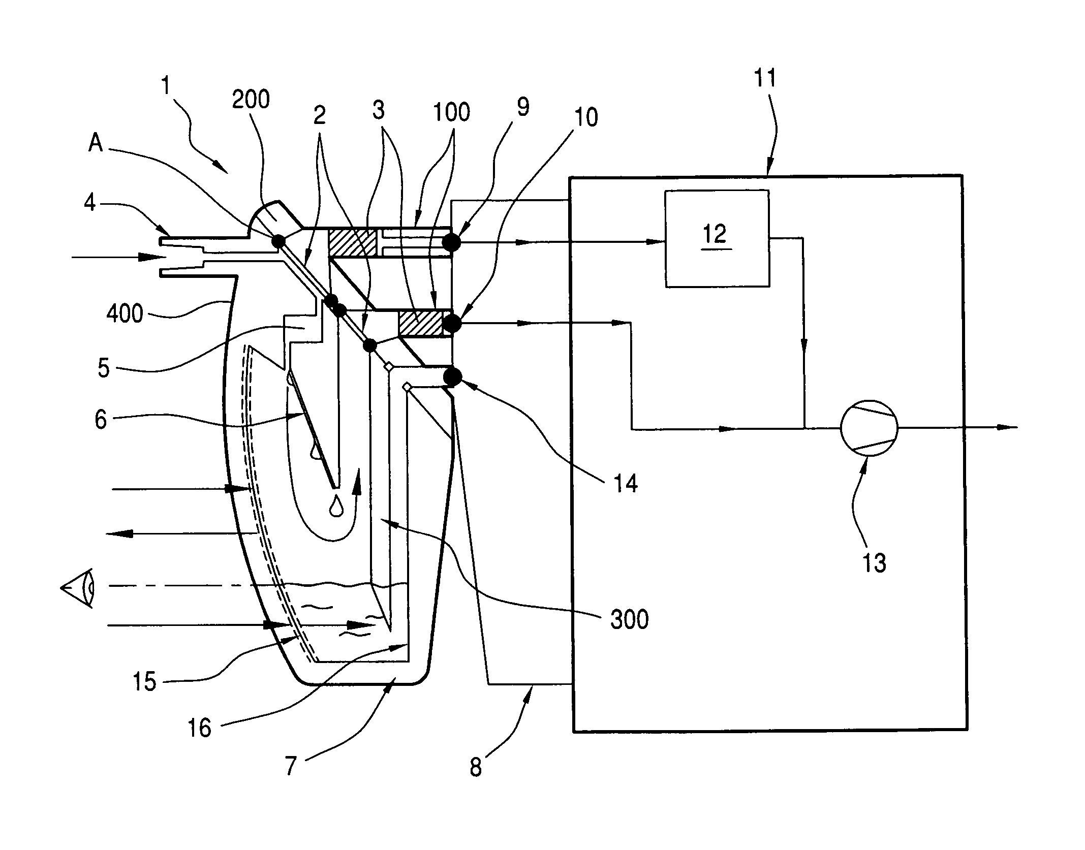
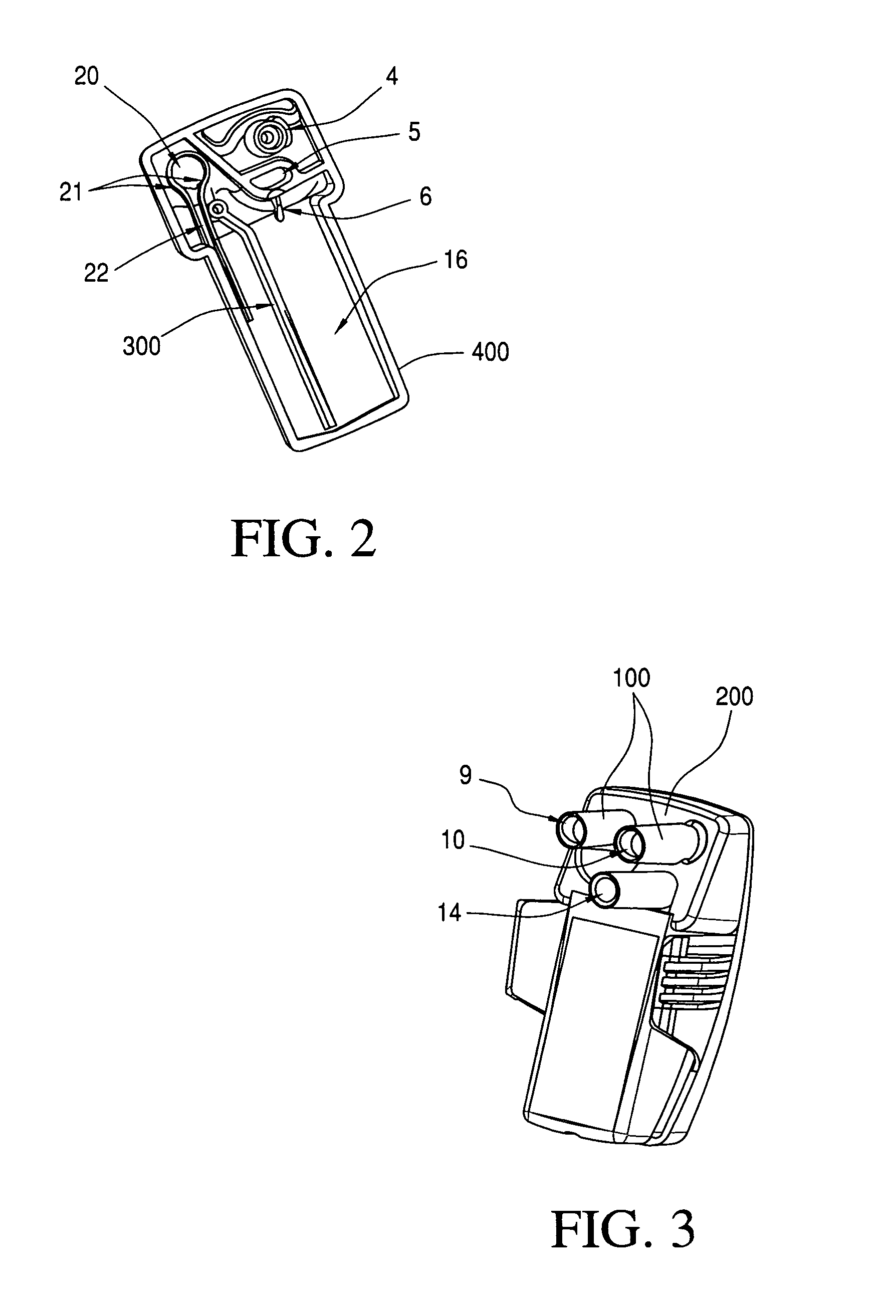
[0027]The water trap 1 in FIG. 1 is releasably attached to the holder 8. The holder 8 is connected downstream to the gas measuring module 11 via three ports, that is, connections, namely an analysis port 9, a purge port 10 and a service port 14. The gas measuring module 11 has one or more gas sensors 12 to measure the respiratory gas to be analyzed as well as a pump 13 for moving the measurement gas or gas being measured. The gas sensors 12 are, for example, infrared optical sensors to determine the concentration of selected respiratory gas components. The measurement gas flows from an aspiration location (not shown) in a patient-respiratory gas line via the measurement gas inlet 4 into the water trap 1. Via two semipermeable PTFE-membranes 2, the measurement gas is separated from moisture contained therein with the liquid being captured in the tank 7.

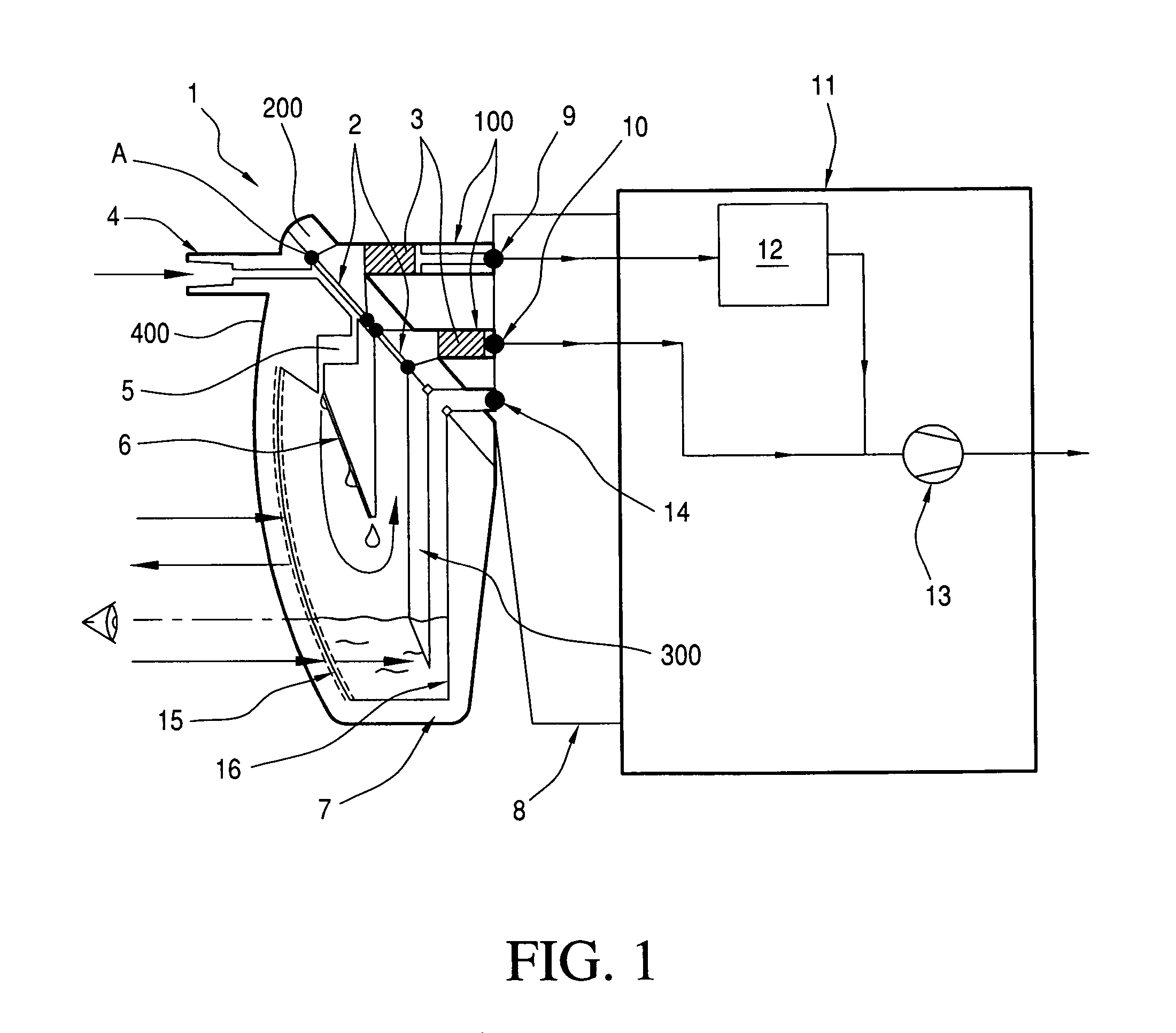
[0028]An intermediate piece 200 is disposed between housing member 400 and the holder 8. As shown in FIG. 1, the two semipermeable me...


PUM


Abstract

A water trap (1) improved with respect to handling and operational safety includes: two semipermeable membranes (2) and at least one tank (7), wherein the membranes have a water penetration pressure greater than 750 hPa and are made of the same or different PTFE laminates. The gas flow is divided in a ratio between 10:90 and 25:75 into the flush- / purge branch and analysis branch to the sensors (12) and a path parallel to the sensors (12), respectively, with the aid of the membranes and downstream filter elements and via the material and configuration.

Description

CROSS REFERENCE TO RELATED APPLICATION[0001]This application claims priority of German patent application no. 10 2009 024 040.3, filed Jun. 5, 2009, the entire contents of which is incorporated herein by reference.FIELD OF THE INVENTION[0002]The invention relates to a water trap with two semipermeable membranes and at least one tank.BACKGROUND OF THE INVENTION[0003]Such water traps are disclosed, for example, in U.S. Pat. No. 6,117,214 and United States patent application publication 2009 / 0084383.[0004]In water traps used hitherto for anesthetic gases or for anaesthetic devices for measuring the respiratory gas of a patient drawn off by suction, either exclusively gas permeable and liquid impermeable PTFE-(Polytetrafluoroethylene)-membranes are used or filter elements are used in addition to a PTFE-membrane. The filter elements are intended to noticeably increase their gas flow resistance when coming in contact with water and to prevent water from penetrating.[0005]Disadvantageous i...

Claims


Application Information

Patent Timeline
Patent Type & Authority Patents(United States)
IPC IPC(8): B01D53/22
CPCA61M16/0808B01D53/268A61M16/085A61M2016/1035A61M2205/584A61M2205/75A61M2205/7536B01D2259/4533
Inventor PETER, GERDMAXEINER, THOMASWUSKE, THOMAS
Owner DRAGERWERK AG
Why Eureka
Try Eureka