Vibration-based power generator

Inactive Publication Date: 2012-07-17
SOUNDS ENERGY SYST
View PDF7 Cites 56 Cited by
  • Summary
  • Abstract
  • Description
  • Claims
  • Application Information

AI Technical Summary

Benefits of technology

[0043]In a further aspect, the variable stiffness oscillator is further adjusted by selecting a distance of

Problems solved by technology

Maintenance, replacement, and disposal of batteries are expensive, time consuming, and environmentally hazardous tasks for large sensor networks.
In fact, these tasks are practically impossible to perform for embedded sensors, such as those embedded inside structures (bridges, roads, buildings) or airframes.
The usability of vibration-based MPGs is severely limited by the random nature of environmental vibrations.
Outside this ban

Method used


Image

  • Vibration-based power generator
  • Vibration-based power generator
  • Vibration-based power generator

Examples


first embodiment

[0102]Turning now to FIGS. 5a to 8b various embodiments of electromagnetic, electrostatic, and piezoelectric MPGs designed according to the present invention will be described.

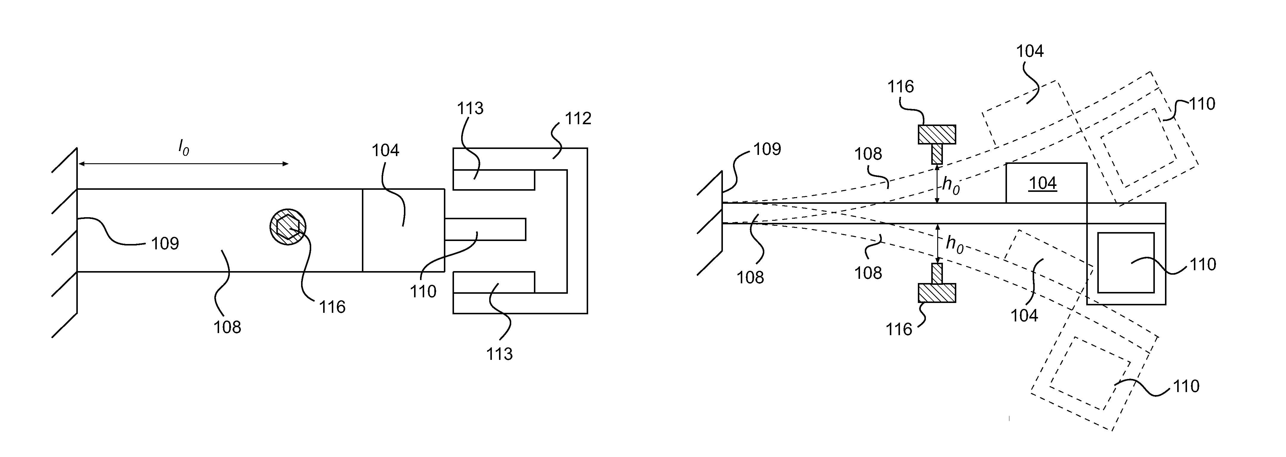
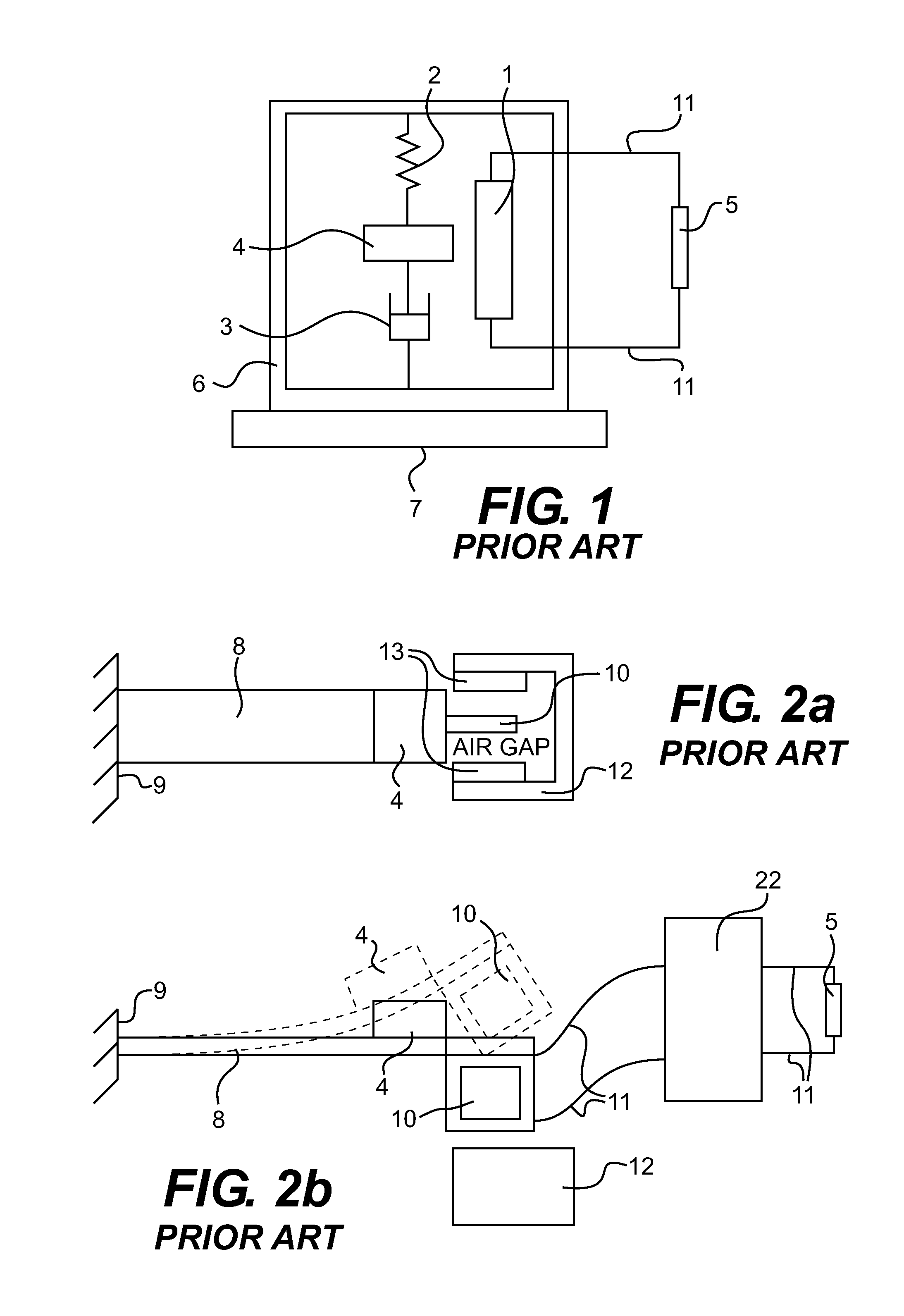
[0103]Referring to FIGS. 5a and 5b, an electromagnetic MPG according to the first embodiment consists of an inertial mass 104, a cantilever beam 108, a coil 110, and magnets 113 attached to a yoke 112, in a similar arrangement to the one described above in the prior art (FIGS. 2a and 2b). Alternatively, the inertial mass 104 could be made of a yoke 112 and magnets 113 assembly while the coil 110 could be stationary (such a version is shown in FIG. 10b). The energy produced by the coil 110 and magnet 113 arrangement is routed through electric connectors 111 to a power conditioning circuit 122 and then to a storage device or an electric load 105.

[0104]The electromagnetic MPG of the first embodiment of the invention, is further equipped with a subsystem consisting of a rigid stopper 116 in the vicinity of the mov...

fourth embodiment

[0125]A second version of an electromagnetic MPG according to the invention is presented in FIGS. 16a and 16b. In this alternative version, a single spring 102 is used instead of the cantilever beam 108. The spring 102 supports the magnet 113 which acts as the inertial mass 104 of the MPG. It is contemplated that any spring 119 with a hardening nonlinearity could be used to construct this MPG. The stopper 116 is placed on the upper part of the base 109 so as to contact the magnet 13 when the strike exceeds a threshold amplitude ho.

[0126]A piezoelectric MPG according to the fourth embodiment of the invention is shown in FIGS. 17a, and 17b. Similarly to the electromagnetic MPG according to the fourth embodiment, the rigid stopper 116 is placed directly within the envelope of motion of the inertial mass 104 of a piezoelectric MPG.

[0127]Referring now to FIGS. 19a and 19b, a MPG designed according to a fifth embodiment of the invention will be described. In this fifth embodiment, the ine...

sixth embodiment

[0129]In a second version of the invention, shown in FIGS. 22a and 22b, the MPG comprises a piezoelectric transduction mechanism. A single rigid stopper 116 is placed above (or below) one of the two beams 108 (or tethers) supporting the inertial mass 104. This configuration creates a two-stage nonlinear spring. As a result, the hardening-type nonlinearity of the harvesting element grows thereby enhancing the hardening-type behavior of the oscillator and further expanding the up-sweep bandwidth of the MPG.

[0130]A third version of the sixth embodiment of the invention is shown in FIGS. 23a and 23b. In this third version, two rigid stoppers 116 are asymmetrically placed above (or below) two beams 108 (or tethers) supporting the inertial mass 104 of an electrostatic MPG. Each stopper 116 is placed within the envelope of motion of each beam 108 to create a three-stage nonlinear spring with three increasingly stiffer stages. As a result, the hardening-type nonlinearity of the harvesting e...


PUM


Abstract

A vibration-based power generator has a variable stiffness oscillator connected to a base. The oscillator comprises an inertial mass moving relative to the base in response to vibrations. The oscillator has a neutral position corresponding to a position of the oscillator when no vibrations are transmitted to the base. The oscillator has a first position where the mass is at a first distance and a second position where the inertial mass is at a second distance from a position of the mass when the oscillator is in neutral position. The second distance is greater than the first distance. A stiffness of the oscillator at the second position is greater than a stiffness of the oscillator at the first position. A transducer generating electric power in response to movement of the inertial mass is associated with the oscillator. A method of optimizing a vibration-based power generator is also presented.

Description

CROSS-REFERENCE[0001]This application claims priority from U.S. Provisional Application No. 61 / 071,957, filed May 28, 2008, the entirety of which is incorporated by reference.FIELD OF THE INVENTION[0002]The present invention is related to an apparatus for energy harvesting, more specifically for harvesting energy from waste or environmental vibrations.BACKGROUND OF THE INVENTION[0003]Batteries are the power source of choice for many sensor systems. Maintenance, replacement, and disposal of batteries are expensive, time consuming, and environmentally hazardous tasks for large sensor networks. In fact, these tasks are practically impossible to perform for embedded sensors, such as those embedded inside structures (bridges, roads, buildings) or airframes. Using micro-power generators (MPGs) to recharge batteries or alternative energy storage devices is an effective solution to this problem. In addition, MPGs can supply energy at higher levels than batteries which allows localized compu...

Claims


Application Information

Patent Timeline
IPC IPC(8): F03D5/04
CPCF03G7/08H02N2/186H02K35/00
Inventor SOLIMAN, MOSTAFAABDEL-RAHMAN, EIHAB MOHAMEDMANSOUR, RAAFAT R.EL-SAADANY, EHAB FAHMY
Owner SOUNDS ENERGY SYST
Why Eureka
Try Eureka