Adaptive pulse width time domain reflectometer

a time domain reflectometer and pulse width technology, applied in the field of time domain reflectivity (tdr) methods, can solve the problems of increasing the difficulty of telephone technicians to discriminate, the difficulty of detecting anomalies, and the communication lines or cables that work sufficiently well for standard telephones do not always work well for different types of dsls. achieve the effect of improving the user interface of acquired data, reducing the number of gain and distance ranges

Active Publication Date: 2012-07-17
VIAVI SOLUTIONS INC
View PDF17 Cites 67 Cited by
  • Summary
  • Abstract
  • Description
  • Claims
  • Application Information

AI Technical Summary

Problems solved by technology

Communication lines or cables that work sufficiently well for standard telephone do not always work well for different types of DSL.
An impedance discontinuity often corresponds to a fault in the communication cable.
As the transmission lines under investigation become longer, electrical signal loss in the line increases so that it becomes increasingly harder to detect such anomalies.
In most cases it takes considerable training and practice for a telephone technician to discriminate between the various anomalies.
A narrow pulse into a long cable experiences so much attenuation that the reflections become practically undetectable.
Wider pulses are however limited in their the capability to resolve closely spaced multiple discontinuities such as opens, shorts or bridged-taps (BT).
With Step TDR the return signals become considerably more difficult to interpret as the complexity for a network of cables increases.
There are some practical limitations of the above technique that stem from the attenuation, pulse spreading and slower rise times of the return signals when the fault to be detected is located at long distances in the line under test 8.
This can be not only labor intensive and time consuming, but also carry an increased risk of overlooking or missing the detection of some faults.

Method used


Image

  • Adaptive pulse width time domain reflectometer
  • Adaptive pulse width time domain reflectometer
  • Adaptive pulse width time domain reflectometer

Examples


Embodiment Construction

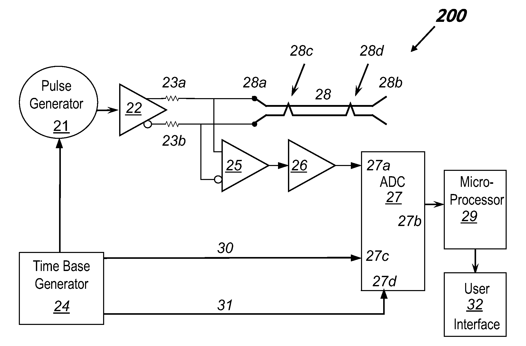
[0041]To address the problems associated with prior art time-domain reflectometer (TDR) techniques, the present invention is based on a modified Step TDR 200 shown in FIG. 5. A pulse generator 21 is used to generate one or more launch pulses with a pulse width ranging from about 10 nanoseconds up to a millisecond or more.

[0042]For balanced lines as in a telephone system, the pulse generator 21 differentially drives the cable under test 28 with a differential output line driver 22 through a pair of impedance matching resistors 23a, 23b. A differential launch pulse is injected at a start time into the near-end 28a of the cable or line under test 28, where it propagates towards the far-end 28b. Any faults in the form of impedance discontinuities 28c, 28d will cause a reflected wave that will arrive back at the near-end 28a as a return voltage signal, where it is received by an input of a differential receiver 25 at an arrival time subsequent to the start time depending on the location ...


PUM


Abstract

An adaptive pulse width (APW) Time Domain Reflectometer (TDR) comprises an enhancement to the standard Pulse TDR by adjusting the effective pulse width as a function of time. Improved resolution for a large range of cable lengths is obtained, as well as allowing an all-in-one view of the processed return signal trace.

Description

CROSS-REFERENCE TO RELATED APPLICATIONS[0001]The present invention claims priority from U.S. Provisional Patent Application No. 61 / 073,864 filed Jun. 19, 2008, which is incorporated herein by reference for all purposes.TECHNICAL FIELD[0002]The present invention relates to a time domain reflectivity (TDR) method for diagnosing faults in transmission lines of a communication or telephone cable system, and presenting abnormalities on a suitable display for technical maintenance personnel.BACKGROUND OF THE INVENTION[0003]With the demand of higher speed internet access to the home, new technologies known as Digital Subscriber Line (DSL) have been invented. Communication lines or cables that work sufficiently well for standard telephone do not always work well for different types of DSL.[0004]The communication cable can be any copper pair line for use in ISDN DSL (IDSL), Asymmetric DSL (ADSL), High bit rate DSL (HDSL), Symmetric DSL (SDSL), Single-Pair High-speed DSL (SHDSL), and (Very Hi...

Claims


Application Information

Patent Timeline
Patent Type & Authority Patents(United States)
IPC IPC(8): G01R31/11
CPCG01R31/11H04L41/0677H04M3/304H04M11/062
Inventor WYAR, PAUL FRANCISWILLIAMS, JOHN GARFIELD
Owner VIAVI SOLUTIONS INC
Why Eureka
Try Eureka