Gamut mapping which takes into account pixels in adjacent areas of a display unit

a display unit and map technology, applied in the field of gamut mapping in display units, can solve the problems of image degradation, blurriness or loss of local contrast, and the structure is not cost-effective, so as to reduce the luminance of the surrounding subpixel, reduce the repetition processing of unchanged image portions, and reduce the contrast with the line

Active Publication Date: 2012-07-17
SAMSUNG DISPLAY CO LTD
View PDF16 Cites 10 Cited by
  • Summary
  • Abstract
  • Description
  • Claims
  • Application Information

AI Technical Summary

Benefits of technology

[0030]FIG. 6 shows an alternative embodiment, in which scaling (444), gamut clamping (450), and determining BL value (430) are performed after the SPR. Here the SPR output can be stored in a frame buffer 610, and the operations 410, 420, 454 can be performed, in each frame, only on the changed portions of the image (the changed portions can be determined before the operation 410.) This embodiment reduces replicate processing of unchanged image portions. However, the gamut clamping (450) may lead to a loss of local contrast as described above, and this loss is not corrected by the sharpening operations performed in conjunction with the SPR. Therefore, in some embodiments of the present invention, other types of sharpening are performed by block 450, particularly for diagonal lines. For example, suppose that the diagonal line D (FIG. 5) is a dark line surrounded by bright saturated colors. Bright saturated colors are likely to be out of gamut because their luminance cannot be fully shared by the white subpixels. The dark line D will likely be in-gamut. A conventional gamut clamping operation would reduce the luminance of the surrounding subpixels to reduce the contrast with the line D and possibly make the line D almost invisible. In some embodiments, the gamut clamping detects dark diagonal lines on bright saturated surround and reduces the dark diagonal lines' luminance to improve the local contrast.
[0031]The present disclosure provides embodiments that improve image quality at relatively low cost. More particularly, circuit320 can be constructed to analyze the image 104 and provide relatively good image quality for many types of image, and such circuits are within the scope of the present teachings, but such circuits can be large and / or complex and / or slow. In some embodiments, the image analysis is simplified to provide high image quality for many, but a fewer number of different types of images at reasonable cost.

Problems solved by technology

This structure is not cost-effective however because it does not match the resolution of human vision.
The luminance shifts performed in the sub-pixel rendering may undesirably cause image degradation such as blurriness or loss of local contrast.
Further, some of the operations described above may cause some subpixel values to be out of gamut, especially if the gamut is restricted in brightness to reduce power consumption.
Aggressive DBLC may lead to a loss of contrast.
This is inefficient in various respects including power consumption, use of data processing resources (e.g. microprocessor resources in circuit 320), the time needed to display changes in the image, etc.
This however is difficult in the embodiment of FIG. 4 because even small changes in the image may affect the maximum value of the RGBW coordinates generated by block 420, and hence may affect the BL value generated by block 430.
However, the gamut clamping (450) may lead to a loss of local contrast as described above, and this loss is not corrected by the sharpening operations performed in conjunction with the SPR.
Bright saturated colors are likely to be out of gamut because their luminance cannot be fully shared by the white subpixels.

Method used


Image

  • Gamut mapping which takes into account pixels in adjacent areas of a display unit
  • Gamut mapping which takes into account pixels in adjacent areas of a display unit
  • Gamut mapping which takes into account pixels in adjacent areas of a display unit

Examples


Embodiment Construction

[0045]The embodiments described in this section illustrate but do not limit the invention.

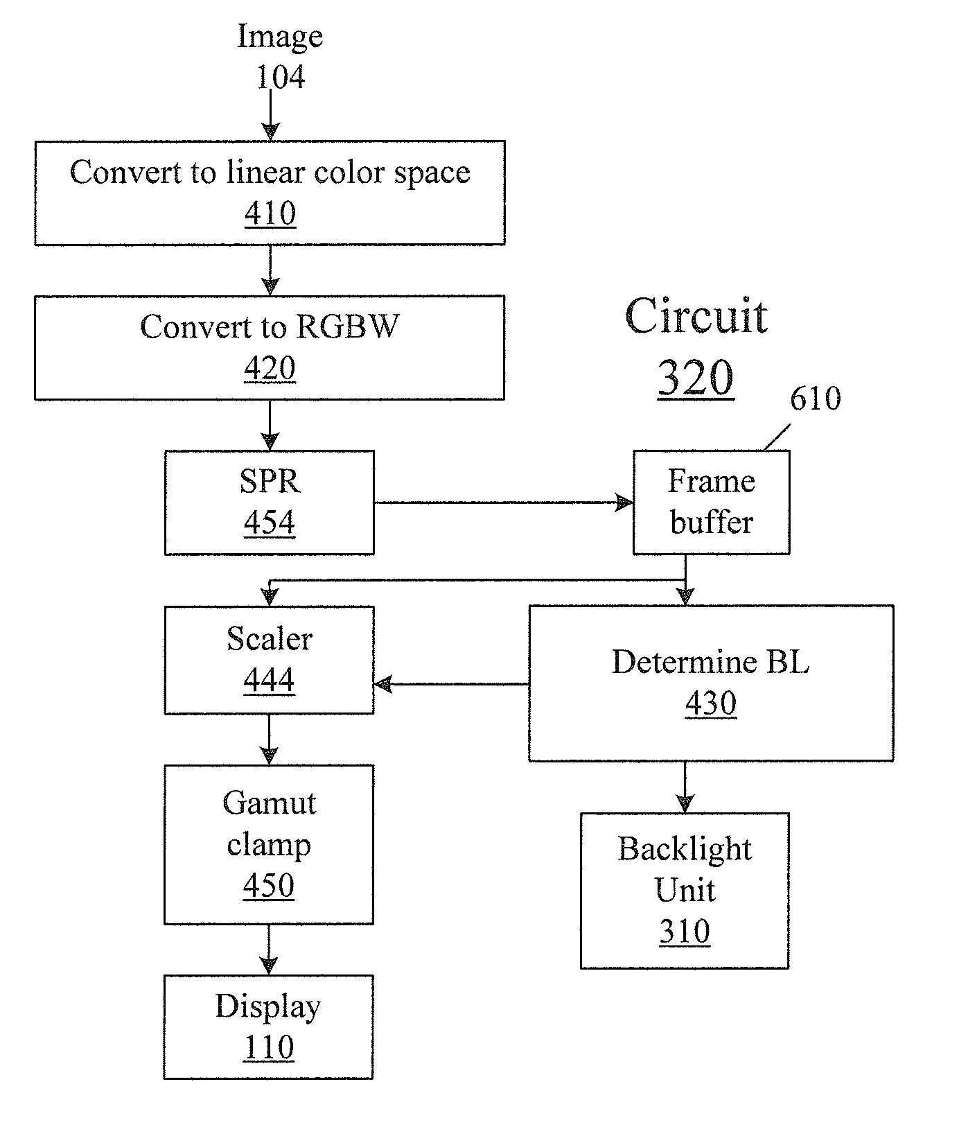
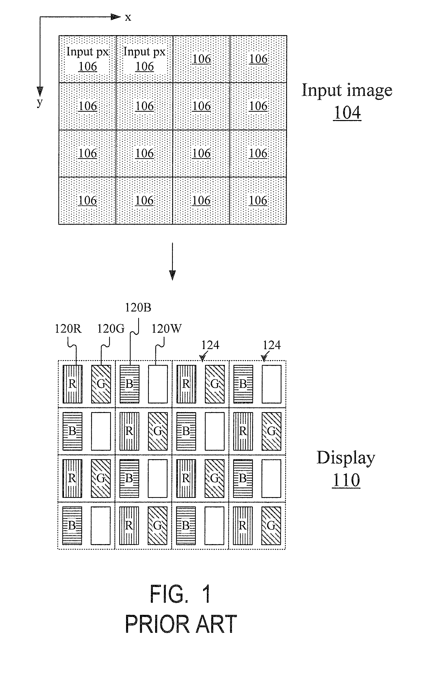
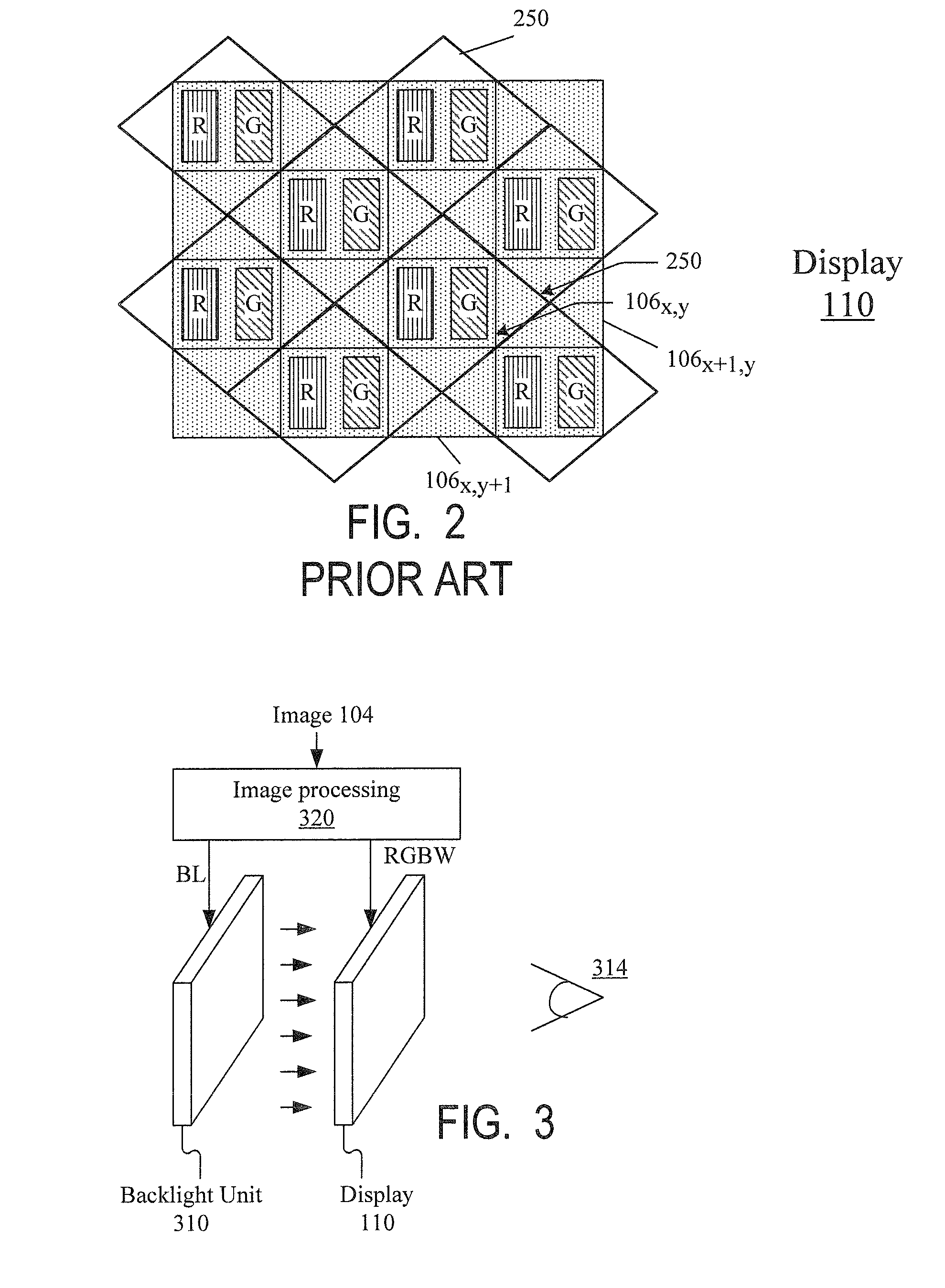
[0046]Some embodiments of the present invention will now be described on the example of the display unit 110 of FIGS. 1 and 3. The data processing will be assumed as in FIG. 4 or 6.

[0047]Conversion to RGBW (step 420). For the sake of illustration, let us suppose that block 410 outputs, for each pixel 106, color coordinates r, g, b in a linear RGB color space. Each of the r, g, b coordinates is an integer allowed to vary from 0 to some maximum number MAXCOL inclusive. For example, if r, g, and b are represented in 8 bits, then MAXCOL=255. In some embodiments, the color coordinates are stored in more bits to avoid loss of precision. For example, if the pixel colors are initially represented in a non-linear color space (e.g. sRGB), with each coordinate being an 8-bit value, then conversion to the linear RGB color space (“gamma conversion”) may produce fractional values for r, g, and b. To reduce q...


PUM


Abstract

A gamut mapping operation (910) detects in-gamut areas surrounded on at least two sides by out-of-gamut areas, and (920, 940) provides additional reduction of the subpixel values in the in-gamut areas to regain some of the contrast between the in-gamut and out-of-gamut areas. Other embodiments are also provided.

Description

BACKGROUND OF THE INVENTION[0001]The present invention relates to gamut mapping in display devices.[0002]Novel sub-pixel arrangements are disclosed for improving the cost / performance curves for image display devices in the following commonly owned United States patents and patent applications including: (1) U.S. Pat. No. 6,903,754 (“the '754 patent”) entitled “ARRANGEMENT OF COLOR PIXELS FOR FULL COLOR IMAGING DEVICES WITH SIMPLIFIED ADDRESSING;” (2) United States Patent Publication No. 2003 / 0128225 (“the '225 application”) having application Ser. No. 10 / 278,353 and entitled “IMPROVEMENTS TO COLOR FLAT PANEL DISPLAY SUB-PIXEL ARRANGEMENTS AND LAYOUTS FOR SUB-PIXEL RENDERING WITH INCREASED MODULATION TRANSFER FUNCTION RESPONSE,” filed Oct. 22, 2002; (3) United States Patent Publication No. 2003 / 0128179 (“the '179 application”) having application Ser. No. 10 / 278,352 and entitled “IMPROVEMENTS TO COLOR FLAT PANEL DISPLAY SUB-PIXEL ARRANGEMENTS AND LAYOUTS FOR SUB-PIXEL RENDERING WITH S...

Claims


Application Information

Patent Timeline
Patent Type & Authority Patents(United States)
IPC IPC(8): G09G5/02
CPCG09G3/3406G09G2340/06G09G2330/10
Inventor ELLIOTT, CANDICE HELLEN BROWNHIGGINS, MICHAEL FRANCIS
Owner SAMSUNG DISPLAY CO LTD
Why Eureka
Try Eureka