
Electroacoustic transducer having multi-channel diaphragm and hearing aid using the same

a technology of electroacoustic transducers and hearing aids, which is applied in the direction of transducer diaphragms, bridges, instruments, etc., can solve the problems of increasing power consumption somewhat, and achieve the effect of low power design and simplified construction of hearing aids

Inactive Publication Date: 2012-07-17
SONG CI MOO
View PDF3 Cites 4 Cited by
  • Summary
  • Abstract
  • Description
  • Claims
  • Application Information

AI Technical Summary

Benefits of technology

This approach reduces power consumption and simplifies the hearing aid design by customizing the transducer to individual hearing characteristics without the need for complex signal processing, enhancing user satisfaction and battery life.

Problems solved by technology

As a result, there is a problem in that power consumption increases somewhat, so the user of the hearing aid must frequently change the battery thereof.

Method used


Image

  • Electroacoustic transducer having multi-channel diaphragm and hearing aid using the same
  • Electroacoustic transducer having multi-channel diaphragm and hearing aid using the same
  • Electroacoustic transducer having multi-channel diaphragm and hearing aid using the same

Examples


first embodiment

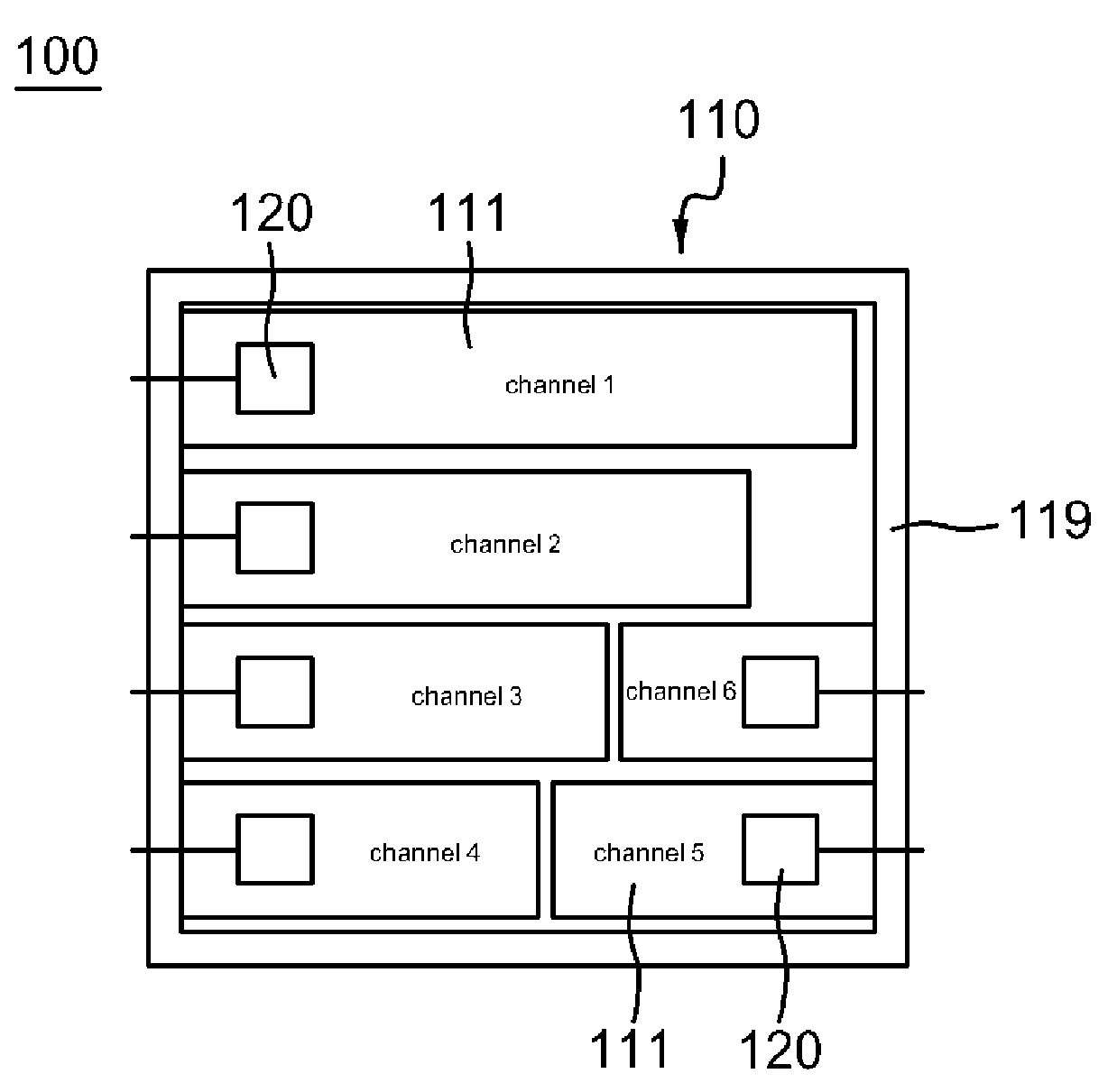
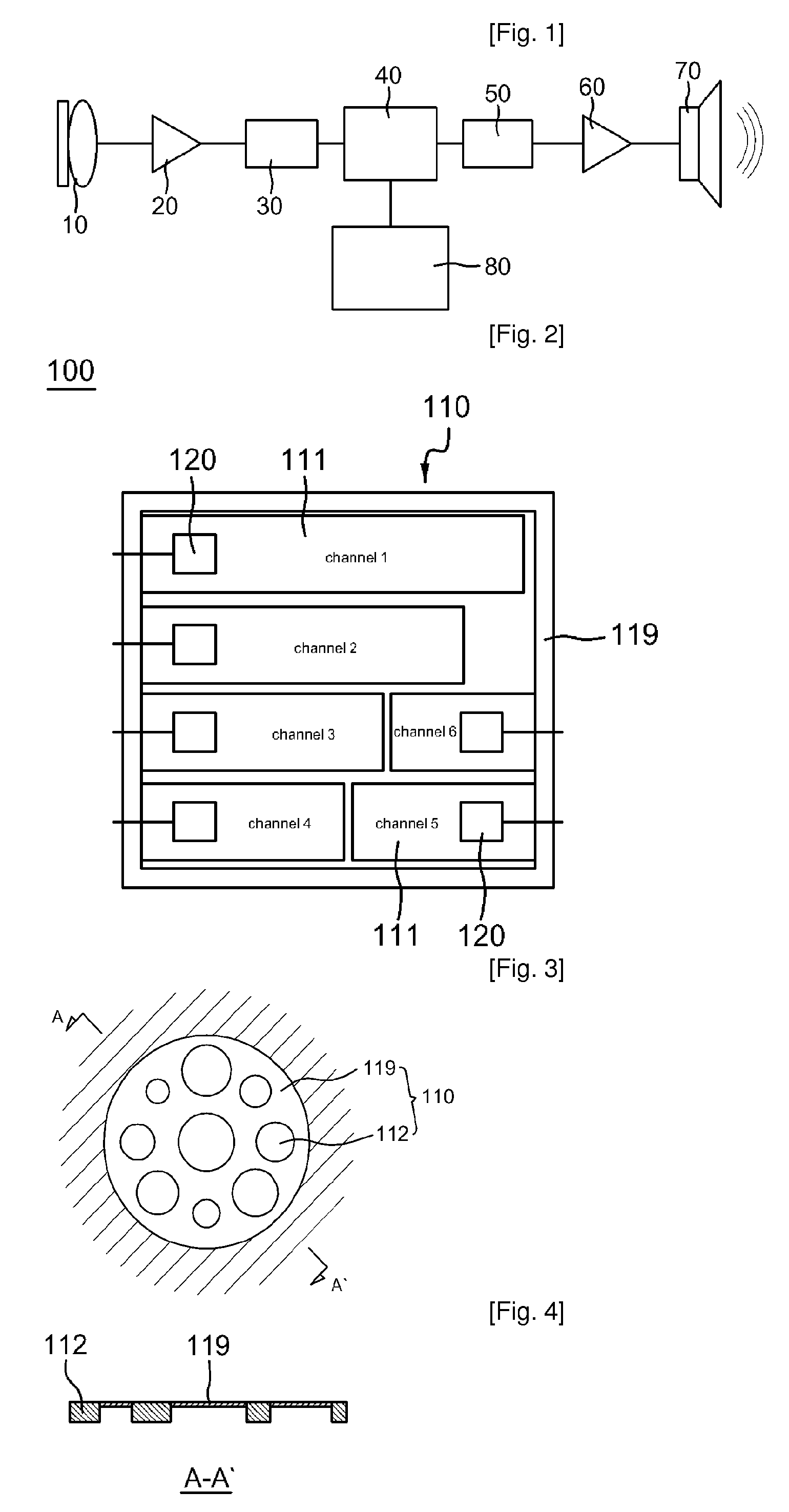
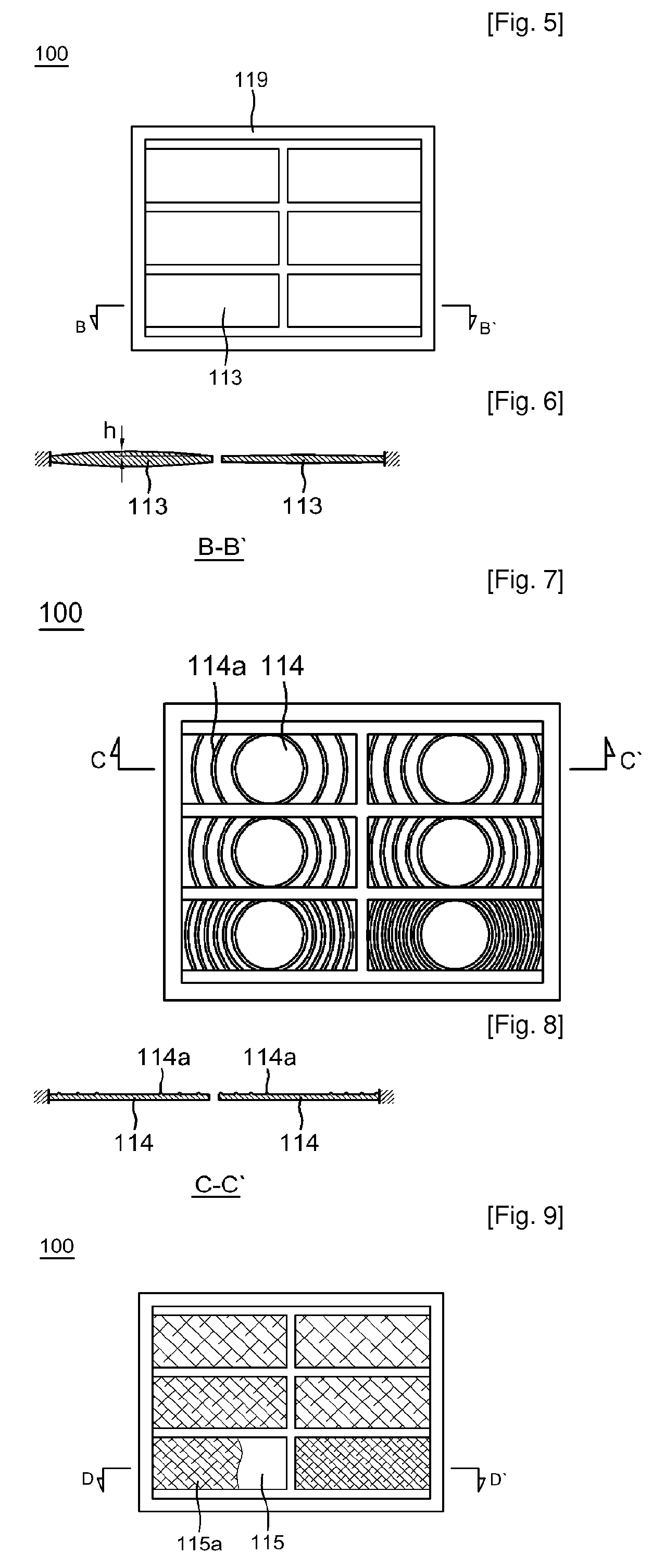
[0031]FIG. 2 is a diagram of an electroacoustic transducer 100 having a multi-channel diaphragm according to the present invention. Referring to FIG. 2, the electroacoustic transducer 100 includes a multi-channel diaphragm 110 and a plurality of signal conversion units 120. The multi-channel diaphragm 110 is constructed so that a plurality of channels 111 having different thicknesses or shapes so as to have different resonant frequencies is formed on the top or sides of a support 119. Each channel 111 formed in the support 119 in this way functions as a single acoustic filter, acoustic amplifier or acoustic attenuator, thus simplifying the construction of a circuit for transmitting an acoustic signal in the air to the channels 111 or transmitting a vibration signal from the channels 111 to the air. Meanwhile, the resonant frequency, frequency band and attenuation constant (Q-factor) of each channel 111 are determined according to the result of measurement of the hearing ability of a...

second embodiment

[0051]The microphone-type electroacoustic transducer 100a and the first amplifiers 150 have the same construction as the microphone-type electroacoustic transducer and the first amplifiers of the second embodiment, so a detailed description thereof is omitted, and the same reference numerals are used.

[0052]The multiplexer 310 is connected to the first amplifiers 150 to receive electrical signals amplified by the first amplifiers 150, and to output only an electrical signal corresponding to a frequency band selected through the user's manipulation.

[0053]The second amplifier 320 amplifies the signal output from the multiplexer 310, and the speaker 330 converts the electrical signal amplified by the second amplifier 320 into acoustic signals.

[0054]FIG. 17 is a diagram showing a hearing aid according to a fourth embodiment of the present invention. Referring to FIG. 17, a hearing aid 400 according to the fourth embodiment of the present invention includes a microphone 410, a first ampli...


PUM


Abstract

An object of the present invention is to provide an electroacoustic transducer having a multi-channel diaphragm, and a hearing aid using the electroacoustic transducer, in which a plurality of channels having different resonant frequencies is formed in the diaphragm using MEMS technology, thus more closely approximating the different audible frequency characteristics of respective persons. The present invention provides an electroacoustic transducer provided with a multi-channel diaphragm. The electroacoustic transducer includes a diaphragm (110) and signal conversion units (120). The diaphragm is provided with respective channels having different resonant frequencies. The signal conversion units are attached to surfaces channels of the channels, or are arranged to be spaced apart from the surfaces of the channels at a predetermined interval, the signal conversion units converting vibration received from the channels into acoustic signals, or transmitting acoustic signals to the diaphragm and converting the acoustic signals into vibration.

Description

TECHNICAL FIELD[0001]The present invention relates, in general, to a microphone and microspeaker having a multi-channel diaphragm, and a hearing aid using the microphone and microspeaker and, more particularly, to a microphone and microspeaker, which are each constructed using a diaphragm in which an audible frequency range for human beings is divided into one or more frequency bands, and a plurality of channels using the center frequencies of respective divided frequency bands as resonant frequencies is provided, and a hearing aid using the microphone and the microspeaker.BACKGROUND ART[0002]Generally, a hearing aid is a device which is worn in the ear to supplement hearing ability and is operated to compensate for a user's hearing difficulty by converting an acoustic signal into an electrical signal, by amplifying the electrical signal and by converting the amplified electrical signal into an acoustic signal. As an electroacoustic device for converting an acoustic signal into an e...

Claims


Application Information

Patent Timeline
Patent Type & Authority Patents(United States)
IPC IPC(8): H04R7/06
CPCH04R1/24H04R1/245H04R7/06H04R25/505H04R2430/03E01D2/02E01D19/00E01D2101/285
Inventor SONG, CI-MOO
Owner SONG CI MOO
Learn More