Process for assembling two assemblies, such as aircraft fuselage assemblies

a technology for fuselage assemblies and assembly processes, which is applied in the direction of manufacturing tools, transportation and packaging, drilling/boring measurement devices, etc., can solve the problems of reduced fatigue strength characteristics of the fuselage assembled in this way, high cost, and inability to optimis

Active Publication Date: 2012-07-24
AIRBUS OPERATIONS (SAS)
View PDF18 Cites 14 Cited by
  • Summary
  • Abstract
  • Description
  • Claims
  • Application Information

AI Technical Summary

Benefits of technology

[0018]The purpose of the invention is therefore to offer a procedure which remedies the above mentioned problems relating to implementation options that use existing technologies. More specifically, the purpose of the invention is to provide an assembly process which allows the required pressure to be applied in a simple manner over the overlap zone during the drilling of holes through this zone, in order on the one hand to avoid burring, and on the other hand to avoid swarf entering the interface between the assembled panels, usually coated with interposition sealant.
[0019]In order to do this, the object of the invention is a process for assembling two assemblies by means of multiple fastening devices intended to create a junction between two panels which are at least partly superimposed which belong respectively to the two assemblies and which together form an overlap zone, where the process involves the drilling of multiple holes through the overlap zone, where each of the holes is designed to house one of the fastening components, where the drilling of each hole is achieved using a drilling tool which passes through an associated centring hole made in a drilling grid securely fitted onto the overlap zone, where the drilling tool includes a mandrel for support on the overlap zone as well as an expanding ring which fits against the mandrel over a conical contact surface which, during the application of a relative movement along a central axis of the contact surface between the mandrel and the ring, allows expansion of this ring to occur, ensuring that it is immobilised in the associated centring hole. According to the invention, the application of the relative movement between the expanding ring and the support mandrel is achieved so that, following the immobilisation of the expanding ring in the associated centring hole, it causes a displacement of the mandrel supported against the overlap zone, through the associated centring hole and along the central axis of the conical contact surface in the direction of this overlap zone, in order to exert a pressure on the latter.
[0020]Thus the invention actually provides a simple and clever solution which allows the required pressure to be easily applied over the overlap zone during the drilling of holes through this same zone, in order on the one hand to avoid burring and on the other hand to avoid swarf entering the interface between the assembled panels, which are usually coated with interposition sealant.

Problems solved by technology

On the other hand, double-curvature panels, such as the fuselage panels for an aircraft cockpit are not “developable” and therefore have no rectilinear generatrix; that is, they may not be “unrolled” onto a plane surface.
In addition, the tolerances relating to the assembly and interference of the fastening components are very tight, generally only a few hundredths of a millimeter, so that it is extremely difficult to pre-drill the panels that are intended to form the overlap zone for the two assemblies whilst ensuring that each of the holes is coaxial within the interference tolerance.
The difficulty involved then lies in the fact that the interface assembly must usually be free of any burring or swarf otherwise the fatigue strength characteristics of the fuselage assembled in this way are reduced.
With this type of way of operating both the dismantling / separation and re-assembly operations for the assemblies, and the cleaning / de-burring operations on the latter extend the manufacturing cycle considerably, so that it becomes costly and is not optimised.
Nevertheless, the means generally used to produce this pressure are complex and difficult to put in place on the assemblies to be fixed together by seams, and this is another source of detrimental effects on the manufacturing cycle.
To this end, because of the overall dimensions involved it is relatively difficult to fit these means of applying pressurisation when drilling grids are used, even though widely used in the field under consideration.
Above all it is usually difficult or even impossible to fit them in place on overlap zones with a complex shape, such as overlap zones with double curvature or on assemblies which form so-called “closed” structures where access is difficult.
Finally, means of pressurisation that are available in existing practice are essentially designed to be employed in the context of a fully automated assembly process, and are in no way suitable for manual assembly, for example in which the operator drills the holes manually drills and fits the fastening components in place using appropriate tools.

Method used


Image

  • Process for assembling two assemblies, such as aircraft fuselage assemblies
  • Process for assembling two assemblies, such as aircraft fuselage assemblies
  • Process for assembling two assemblies, such as aircraft fuselage assemblies

Examples


Embodiment Construction

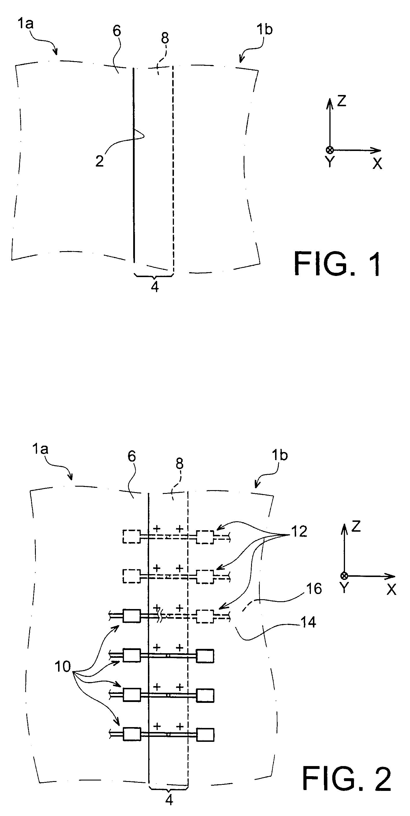
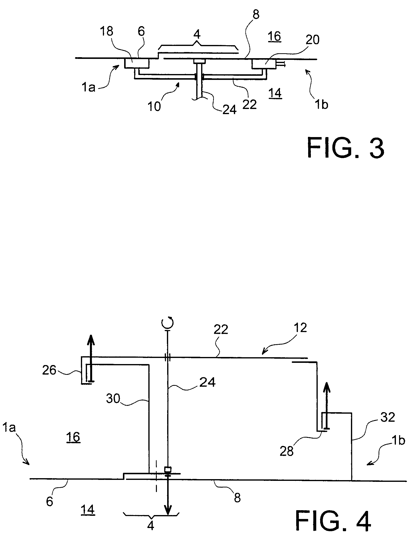
[0091]First of all with reference to FIG. 1, two assemblies 1a, 1b can be seen which are designed to be assembled by so-called orbital seams using rivets and by the implementation of a process according to a preferred means of implementation of the present invention, which will now be described. Here two assemblies 1a, 1b are involved which respectively form two transverse annular sections of an aircraft fuselage, preferably located at the front point or rear end of the aircraft, where the shape of the fuselage has double curvatures.

[0092]In this preferred option for implementation, the process starts, as shown in FIG. 1, with the reference positioning of the two assemblies 1a and 1b, intended to bring the latter together into a set relative position in the reference system of the aircraft, represented here by the references X, Y, Z. The reference positioning is such that it leads to the formation of an overlap zone 4, also known as the junction zone formed by the two panels 6, 8 wh...


PUM

PropertyMeasurementUnit
clamping forceaaaaaaaaaa
pressure forceaaaaaaaaaa

Abstract

A process for assembling two assemblies, for example aircraft fuselage assemblies, using multiple fastening components. The process includes drilling of holes through an overlap zone, carried out using a drilling tool which passes through an associated centering hole made in a drilling grid fixed to this overlap zone, wherein the drilling tool includes a support mandrel and an expanding ring which fits onto the mandrel along a conical contact surface. A relative movement between the expanding ring and the mandrel is applied so that, following immobilization of the ring in the associated centering hole, displacement of the mandrel supported against the overlap zone is produced, through the centering hole and towards this overlap zone, to exert a pressure on the latter.

Description

TECHNICAL FIELD[0001]The present invention relates in general terms to a process for assembling two assemblies, for example by riveting.[0002]The invention applies preferably, but not exclusively, to the assembling of two constituent assemblies of an aircraft fuselage. More precisely, it may involve a so-called seam assembly process, that is to say, assembly by placing a tightened fastening device of the “lockbolt” or rivet type along an interface which is common to the two assemblies, called the overlap zone or junction zone.[0003]As an indication, there is generally a distinction made between so-called orbital seams suitable for assembling two assemblies, in this case called “annular portions” and which are approximately cylindrical in shape, and so-called longitudinal seams which are associated with assembling two assemblies whose shape is effectively a half-cylinder. Longitudinal seams are made along the generatrices of the running section whereas orbital seams are made in an in...

Claims


Application Information

Patent Timeline
Patent Type & Authority Patents(United States)
IPC IPC(8): B21D53/00B21D53/92B23P11/00
CPCB21J15/14B21J15/142B23B47/287B23B49/02B23B2215/04Y10T408/557Y10T29/49947Y10T29/4978Y10T29/49622Y10T29/49778Y10T29/49826B21J15/02B23P19/00B64C1/06
Inventor HOUIS, JEAN-LUCCOHEN BACRI, GERARD
Owner AIRBUS OPERATIONS (SAS)
Why Eureka
Try Eureka