
Active geometry control suspension system and actuating device driving the same

a suspension system and active geometry technology, applied in the direction of threaded fasteners, bolts, transportation and packaging, etc., can solve the problems of vehicle oversteering, controllability deterioration, and difficulty in designing a suspension system layout, so as to reduce weight and cost

Active Publication Date: 2012-07-24
HYUNDAI MOTOR CO LTD
View PDF8 Cites 10 Cited by
  • Summary
  • Abstract
  • Description
  • Claims
  • Application Information

AI Technical Summary

Benefits of technology

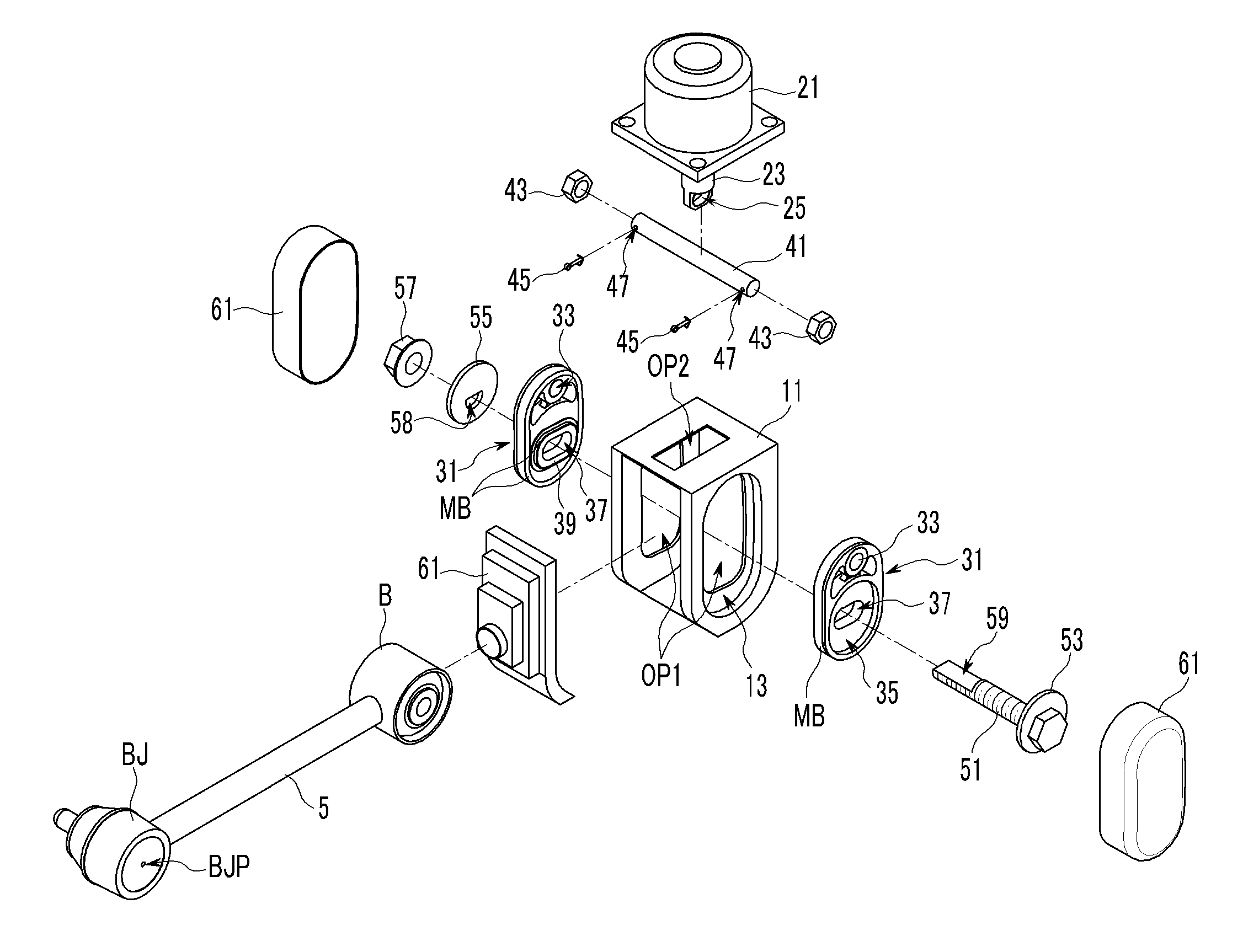
[0023]Various aspects of the present invention are directed to provide an actuating device for an active control suspension system having advantages of reducing weight and cost as a consequence that each slide plate is moved upwardly or downwardly along each slide groove formed at each side of a member bracket of a vehicle body by vertical driving torque of an actuator and the slide plate transmits the vertical driving torque of the actuator to the assist link.
[0024]In addition, another objective of the present invention is that durability of the actuator may be maintained and capacity of the actuator may be minimized by preventing external force from being directly transmitted to the actuator through the assist link.
[0025]Other objective of the present invention is that change in a wheel tread may be minimized and the vehicle body may be controlled optimally by forming the slide groove as arc shape such that a trace of the slide plate follows a circular arc having a rotation center at a connecting point of the assist link to a rear wheel.
[0026]Other objective of the present invention is that an initial toe can be set and controlled without a toe control screw mounted on the assist link by using an eccentric cam-bolt unit for assembling a bush of the assist link with both slide plates.

Problems solved by technology

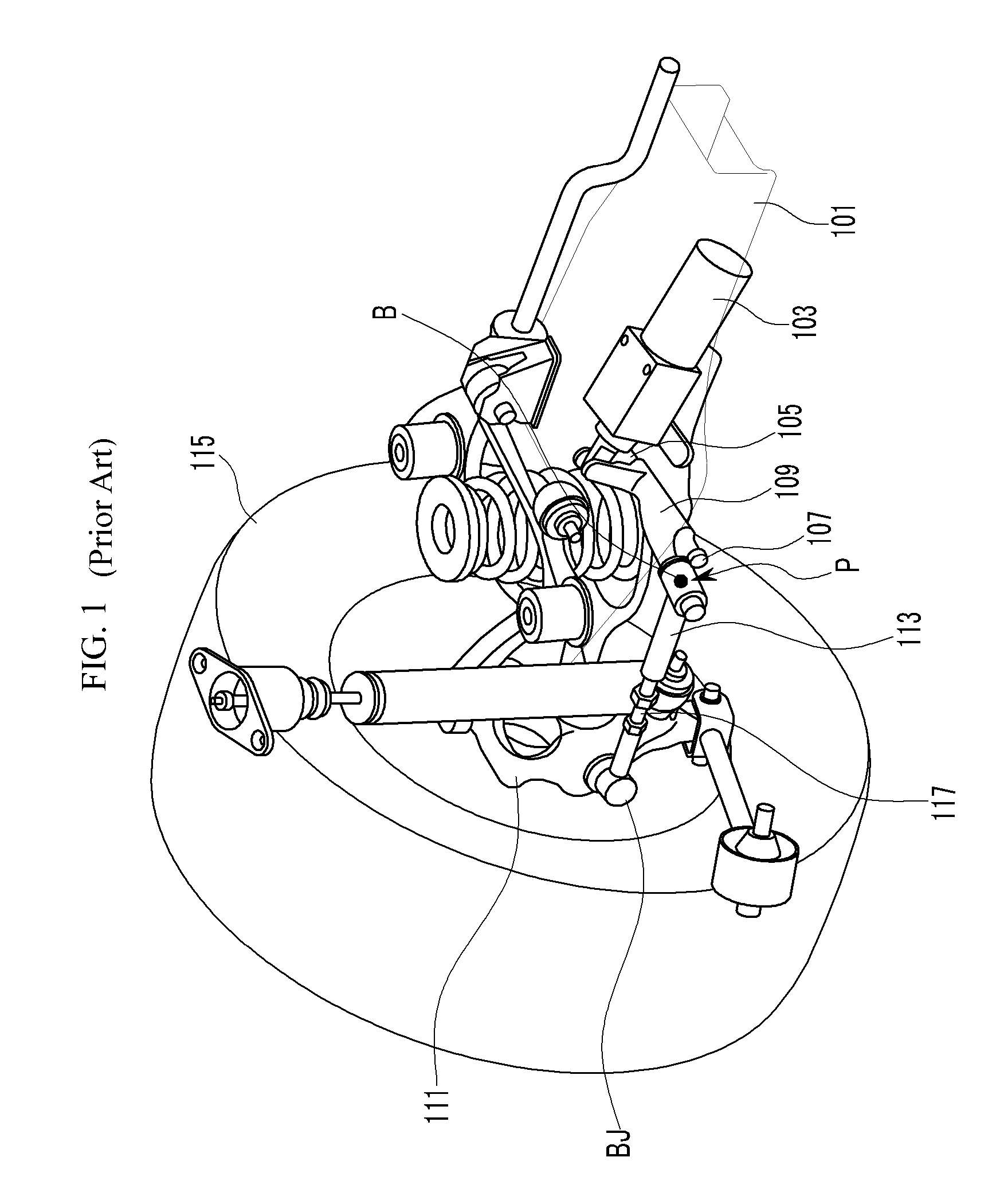
When the vehicle turns quickly, the vehicle oversteers and controllability may be deteriorated.
Therefore, the actuator 103 of large capacity should be used and accordingly it is difficult to design a layout of the suspension system.

Method used


Image

  • Active geometry control suspension system and actuating device driving the same
  • Active geometry control suspension system and actuating device driving the same
  • Active geometry control suspension system and actuating device driving the same

Examples


Embodiment Construction

[0049]Reference will now be made in detail to various embodiments of the present invention(s), examples of which are illustrated in the accompanying drawings and described below. While the invention(s) will be described in conjunction with exemplary embodiments, it will be understood that present description is not intended to limit the invention(s) to those exemplary embodiments. On the contrary, the invention(s) is / are intended to cover not only the exemplary embodiments, but also various alternatives, modifications, equivalents and other embodiments, which may be included within the spirit and scope of the invention as defined by the appended claims.

[0050]Hereinafter, an exemplary embodiment of the present invention will be described in detail with reference to the attached drawings.

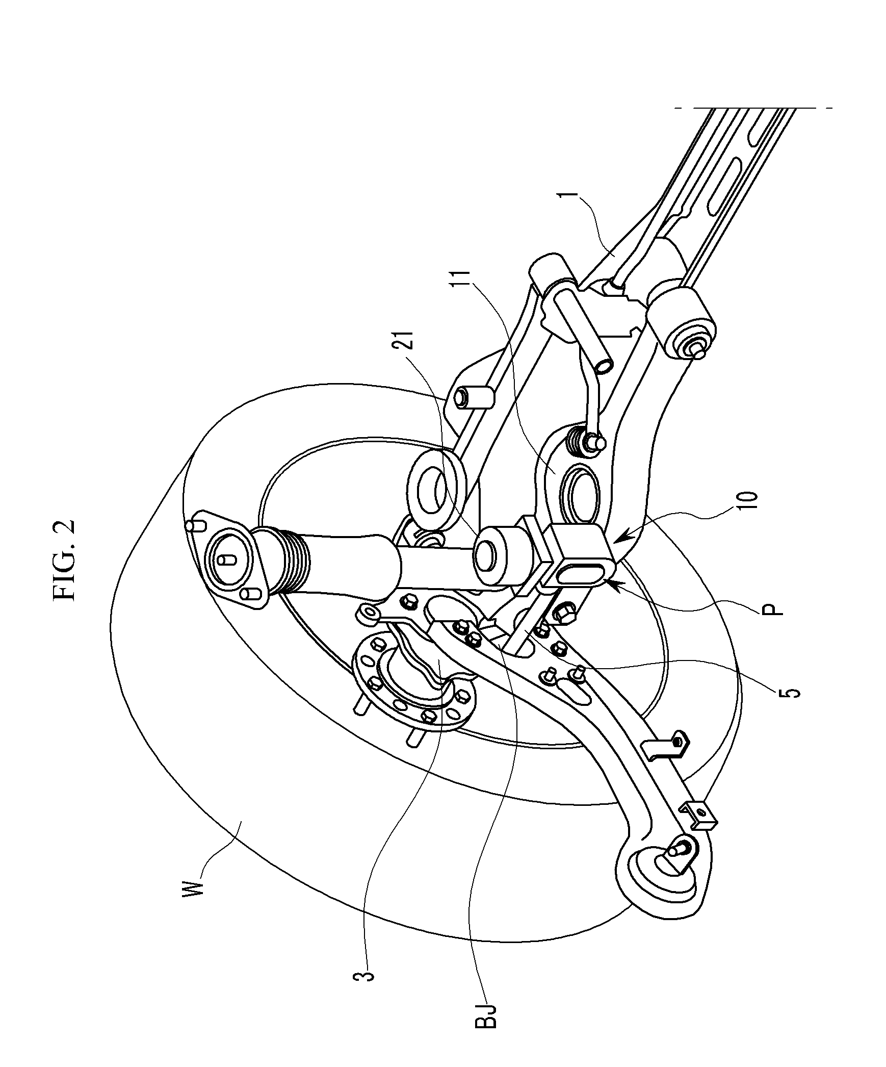
[0051]FIG. 2 is a perspective view showing a part of an active control suspension system having an actuating device according to an exemplary embodiment of the present invention.

[0052]An active contro...


PUM


Abstract

An actuating device for an active control suspension system which is provided at both ends of a sub-frame of a vehicle body and connected to one end of an assist link having the other end mounted at a knuckle and which changes a position of a mounting point of the assist link at the vehicle body, may include a member bracket fixedly mounted at each end of the sub-frame, provided with openings formed at both sides and an upper surface thereof, and formed of a pair of slide grooves having arc shape at the both ends thereof to slidably receive a pair of slide plates therein; an actuator connected to both slide plates through a pin-bolt unit; and a cam-bolt unit assembling a bush of the assist link with both slide plates and setting an initial position of the mounting point of the assist link at the vehicle body.

Description

CROSS-REFERENCE TO RELATED APPLICATION[0001]The present application claims priority to Korean Patent Application No. 10-2010-0028169 filed in the Korean Intellectual Property Office on Mar. 29, 2010, the entire contents of which is incorporated herein for all purposes by this reference.BACKGROUND OF THE INVENTION[0002]1. Field of the Invention[0003]The present invention relates to an actuating device for an active control suspension system (AGCS), and more particularly to an actuating device for an active control suspension system which is connected to one end of an assist link having the other end mounted at a knuckle provided at both ends of a sub-frame of a vehicle body and which changes a position of a mounting point of the assist link at the vehicle body.[0004]2. Description of Related Art[0005]Generally, a suspension system for vehicles is disposed between a vehicle body and a wheel and connects two rigid bodies by using a plurality of links. The suspension system includes a s...

Claims


Application Information

Patent Timeline
Patent Type & Authority Patents(United States)
IPC IPC(8): B60G7/00B62D17/00
CPCB60G7/006B62D17/00B60G2200/462B60G2204/423B60G2202/44
Inventor LEE, UN KOO
Owner HYUNDAI MOTOR CO LTD
Learn More