“O” head design

a discharge head and head technology, applied in the direction of machines/engines, stators, liquid fuel engines, etc., can solve the problems of difficult coupling of shafts, and achieve the effect of increasing the stiffness of the motor stand structur

Active Publication Date: 2012-07-24
ITT MFG ENTERPRISES LLC
View PDF25 Cites 9 Cited by
  • Summary
  • Abstract
  • Description
  • Claims
  • Application Information

AI Technical Summary

Benefits of technology

[0008]The discharge head according to the present invention makes it quicker and easier to couple together the shaft of a pump and the shaft of a motor in such VTSH pumps when compared to the techniques known in the art.
[0012]The discharge head may be configured to provide twice the nozzles loads per API610 standard, including API610-8Th and 10Th Ed., so as to provide discharge head stiffness to withstand API forces and moments.
[0015]The discharge head may be configured to have a shorten height length so as to improve the overall pump vibration due to less cantilever distance from the foundation to the motor top bearing.
[0018]The discharge head may be configured to have a smaller seal housing pipe than the known housing pipes and dimensioned so as to reduce the amount of hydraulic losses, better hydraulic pressure distribution in the elbow transition and facilitates the installation of the mechanical seal or packing arrangement. The discharge head may be configured to have a smaller base plate area, such that the pipe support angle is around 80° versus 60 to 70° from known competitor's device used for high pressure pump applications.
[0023]The present invention provides an increase motor stand structure stiffness for about 2 times API nozzle loads and maximum nozzle flange rating pressure with a maximum relative movement of about 0.003″ between the seal housing and the motor support plate. The current conventional design for the same size analyzed has about 0.012″ relative movement using 1 times API nozzle loads.

Problems solved by technology

One disadvantage of this VTSH pump design, is that the seal housing pipe 14 makes it difficult to couple together the shaft 20a of the pump 20 and the shaft 30a of the motor 30 using the coupling 40.

Method used


Image

  • “O” head design
  • “O” head design
  • “O” head design

Examples


Embodiment Construction

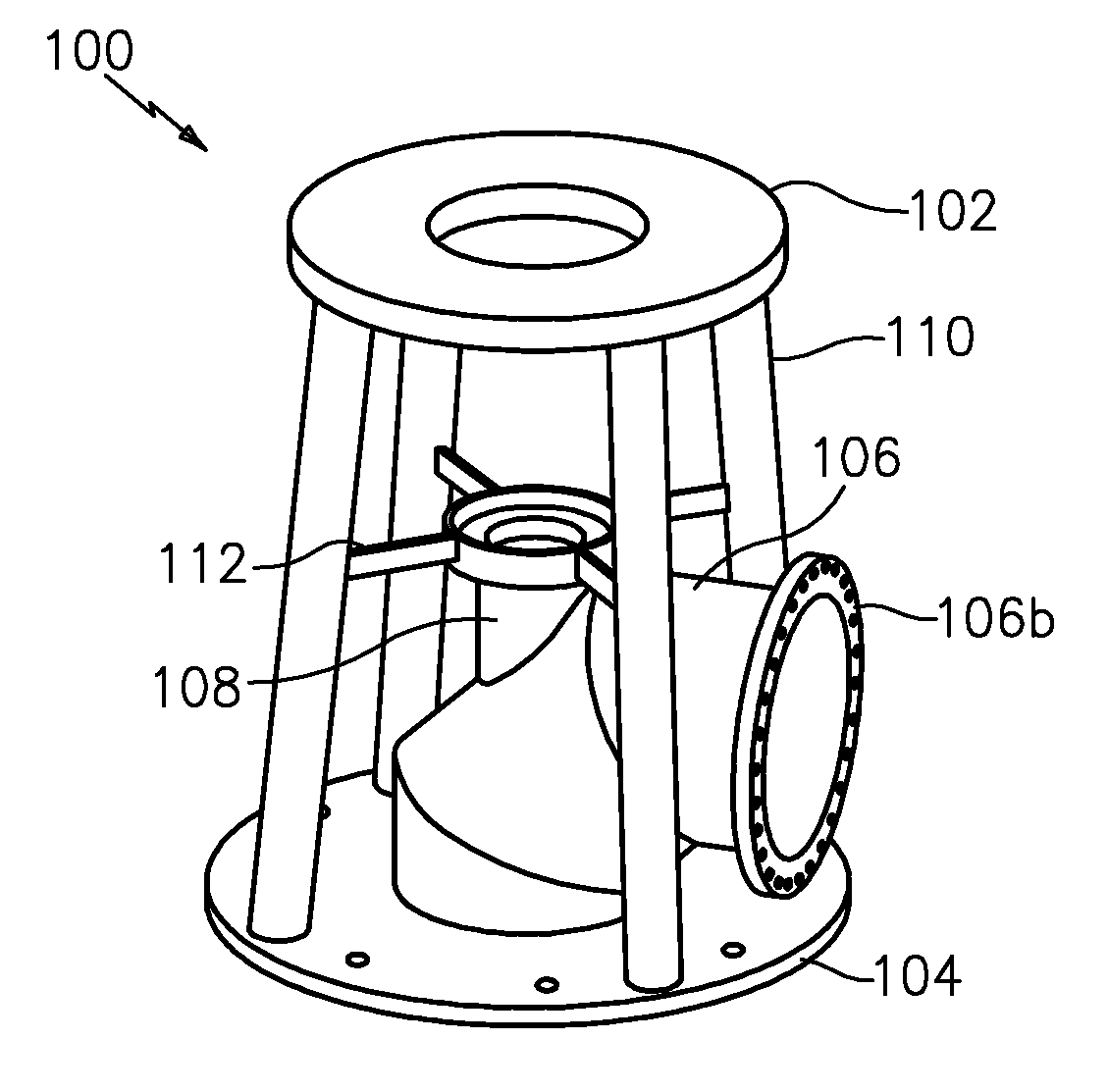
[0032]FIGS. 3-5 show, by way of example, an “O” head design for a discharge head generally indicated as 100 according to some embodiments of the present invention.

[0033]The discharge head 100 feature a motor mounting plate 102 configured for mounting on or to a motor 200 (see FIG. 5); a base plate configured for mounting on or to a pump assembly generally indicated as 300 in FIG. 5; an elbow transition 106 mounted on the base plate 104 configured for providing discharge from the pump assembly 300; a seal housing pipe 108 coupled to the elbow transition 106 configured for receiving a mechanical seal or packing arrangement generally indicated as 400; supporting pipes 110 arranged between the motor mounting plate 102 and the base plate 104; and ribs 112 arranged between the supporting pipes 110 and the seal housing pipe 108 configured to prevent substantially lateral and torsional movement, including movement due to reacting hydraulic forces at a pump nozzle and inertia from a driver.

[...


PUM


Abstract

A discharge head features a motor mounting plate configured for mounting on a motor; a base plate configured for mounting on a pump assembly; an elbow transition mounted on the base plate configured for providing discharge from the pump assembly; a seal housing pipe coupled to the elbow transition configured for receiving a mechanical seal or packing arrangement; supporting pipes arranged between the motor mounting plate and the base plate; and ribs arranged between the supporting pipes and the seal housing pipe configured to prevent substantially lateral and torsional movement, including movement due to reacting hydraulic forces at a pump nozzle and inertia from a driver. The discharge head according to the present invention makes it quicker and easier to couple together the shaft of a pump and the shaft of a motor in such VTSH pumps when compared to the techniques known in the art.

Description

CROSS-REFERENCE TO RELATED APPLICATIONS[0001]This application claims benefit to provisional patent application Ser. No. 61 / 020,902, filed 14 Jan. 2008, which is hereby incorporated by reference in its entirety.BACKGROUND OF THE INVENTION 1. Field of the Invention[0002]The present invention relates to a discharge head; and more particularly to a discharge head for a multistage vertical pump at high pressure, including vertical turbine solids handling (VTSH) pumps. 2. Brief Description of Related Art[0003]VTSH pumps are known in the art which operate in an upright position and employ a bowl assembly including a rotary impeller submerged in a body of liquid or fluid to be pumped having entrained stringy material and other solids. VTSH pumps are typically more efficient over a broad capacity range than conventional solids-handling pumps, and can be used with a wide variety of standard above-ground drives, thus eliminating the need for submersible drives.[0004]By way of example, FIGS. 1 ...

Claims


Application Information

Patent Timeline
Patent Type & Authority Patents(United States)
IPC IPC(8): F04D29/64
CPCF04D13/02F04D29/628F04D29/606F04D13/10
Inventor GUTIERREZ, JOSE RAMONO'DONNELL, RICHARD J.DACH, TIMOTHY MICHAELWEBSTER, STEVEN EDWIN
Owner ITT MFG ENTERPRISES LLC
Why Eureka
Try Eureka