Transmission line for use in magnetic resonance system

a technology of magnetic resonance and transmission line, which is applied in the field of magnetic resonance, can solve the problems of imposing restrictions on the equipment used, unable to provide safe dc-power transmission in the presence of rf fields, and being difficult to use in an mr environment, and the standard electrophysiology catheter, which employs conducting wires for signal transmission, is not usabl

Active Publication Date: 2012-07-24
KONINKLIJKE PHILIPS ELECTRONICS NV
View PDF21 Cites 46 Cited by
  • Summary
  • Abstract
  • Description
  • Claims
  • Application Information

AI Technical Summary

Benefits of technology

[0005]Accordingly, an electrically conductive transmission cable for transmitting a DC signal in the presence of RF fields is disclosed herein. The transmission cable comprises a transmission line including at least a first segment and a second segment, wherein the first and second segments are electrically connected to each other by a reactive coupling unit. The term “reactively coupled” or “reactive coupling” indicates inductive coupling, capacitive coupling or a combination of the two. The reactive coupling unit, therefore, is a unit that is capable of establishing such a reactive coupling or connection between the first and second segments. The reactive coupling unit could be a transformer or an impedance unit such as a capacitor or an inductor. The transmission line may typically be a coaxial cable, though pair lines are also possible. Such a transmission cable is henceforth also referred to as a safe transmission line (STL). The transmission cable is configured to receive a modulated DC signal as an input. A rectifier unit, connected to the transmission line, is configured to extract the DC signal from the modulated DC signal. The extracted DC signal may be supplied to an electrical device or to cardiac tissue for pacing the heart.

Problems solved by technology

Using MR as an imaging modality for guiding catheter interventions imposes restrictions on the equipment used, since conducting structures, like a long metallic wire or cable, inside an MR-system are susceptible to RF-heating, especially at the tip of the conducting structures.
However, providing safe DC-power transmission in the presence of RF fields, as required for example for cardiac pacing or for RF ablation, is more difficult.
Thus standard electrophysiology catheters, which employ conducting wires for signal transmission, are not usable in an MR environment.

Method used


Image

  • Transmission line for use in magnetic resonance system
  • Transmission line for use in magnetic resonance system
  • Transmission line for use in magnetic resonance system

Examples


Embodiment Construction

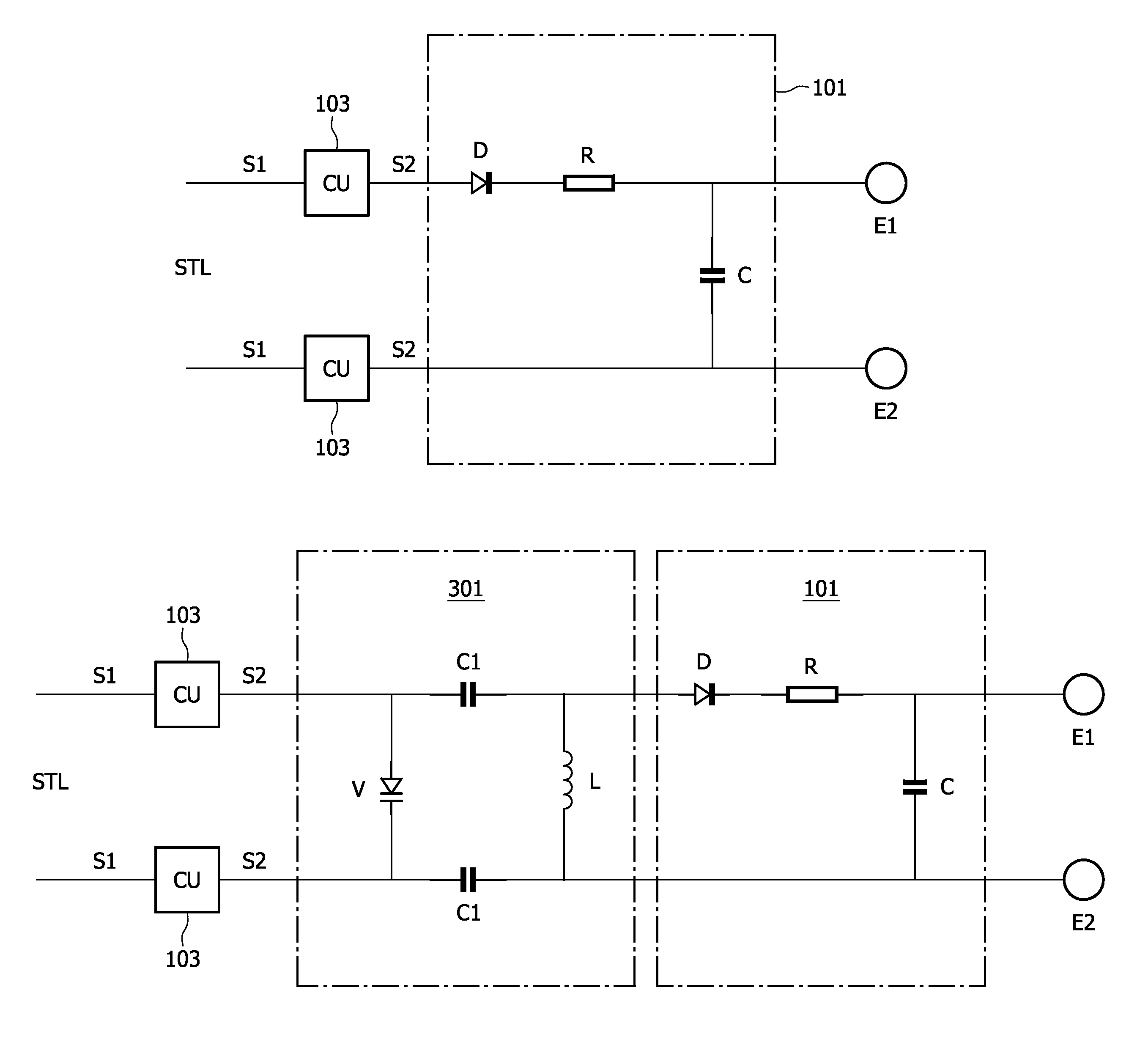
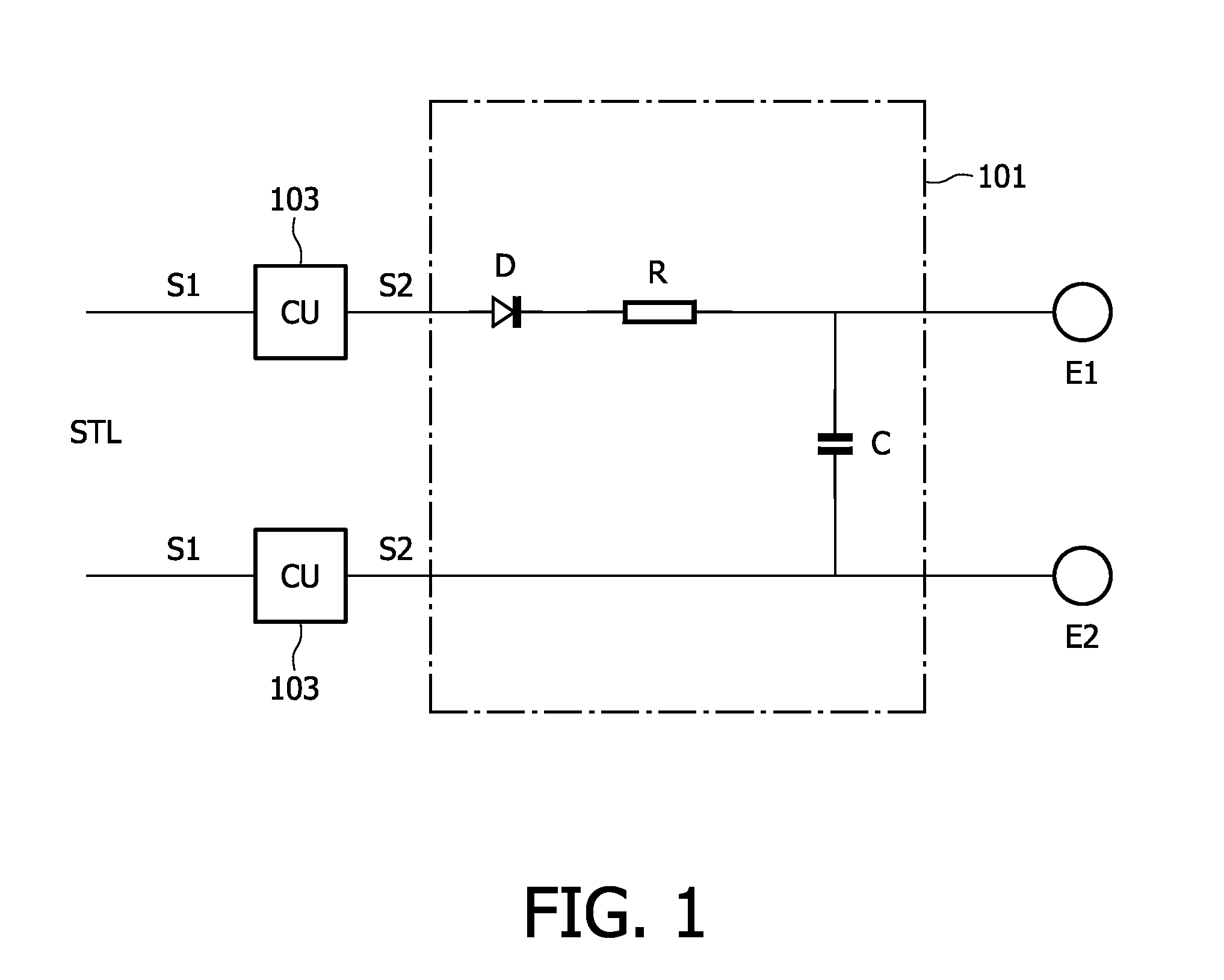
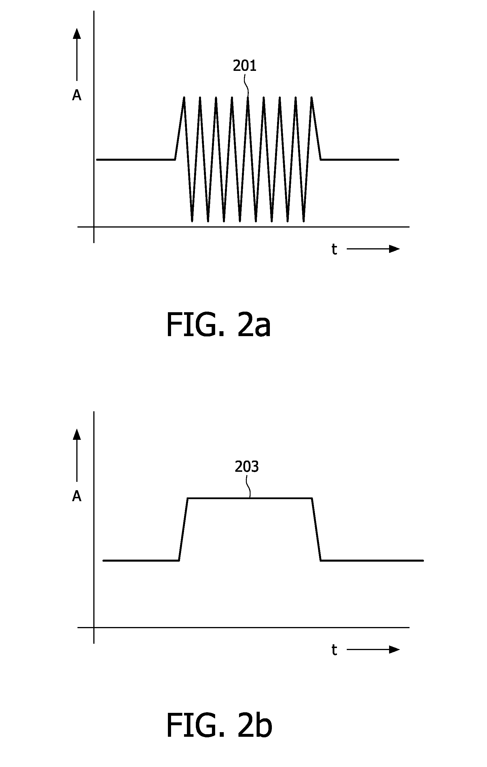
[0013]FIG. 1 shows a possible embodiment of the transmission cable as disclosed herein, used for transmitting DC-power needed for cardiac pacing to the electrodes E1, E2 of a catheter (or other auxiliary interventional device) in an MR-safe manner. A rectifier unit 101 located at the end of the transmission cable proximal to the electrodes E1, E2 rectifies an amplitude-modulated DC signal (201 in FIG. 2a) and extracts a DC signal (203 in FIG. 2b). The transmission cable comprises a first segment S1 and a second segment S2 electrically connected to each other by coupling units (CU) 103. For the purpose of cardiac pacing, the DC signals or pulses typically last several milliseconds and lead to a direct current of a few milliamperes (mA) between the electrodes E1, E2 at the tip of the transmission cable. For other applications, it is possible to generate pulses lasting either for longer or shorter durations. The currents generated at the tip will depend on the resistance between the el...


PUM


Abstract

An electrically conductive transmission cable for supplying a DC signal safely to an electrical device in the presence of radio-frequency (RF) fields in a magnetic resonance (MR) is disclosed herein. The transmission cable comprises a transmission line (STL) comprising at least a first segment (S1) and a second segment (S2), wherein the first and second segments are electrically connected to each other by a reactive coupling unit (103), and a rectifier unit (101) connected to the transmission line and configured to extract the DC signal (203) from the modulated DC signal (201). The extracted DC signal may be supplied to an electrical device or used for cardiac pacing. The transmission cable finds application in auxiliary devices used in an MR environment, for example an interventional catheter with or without an active tracking circuit (301).

Description

FIELD OF THE INVENTION[0001]The invention relates to the field of magnetic resonance (MR), particularly to transmission of electrical currents in the presence of radio-frequency (RF) fields.BACKGROUND OF THE INVENTION[0002]U.S. Pat. No. 7,750,637 discusses a transmission line that is especially provided for connecting an electrical device, like for example an accessory device of an MR imaging system, to a connection unit, like for example a power supply or a control unit. The transmission line is also suitable for connecting implants especially with long conductors or electrodes, like for example heart pacemakers or artificial nerves, for supplying power to preamplifiers, for MR compatible IVUS (intravascular ultrasound) devices, for tracking of catheters or guide wires during MR image generation, and other applications which require a transmission line which is safe when guided through an RF field (for example generated by an MR imaging system). The transmission line comprises at l...

Claims


Application Information

Patent Timeline
Patent Type & Authority Patents(United States)
IPC IPC(8): G01V3/00A61B5/05
CPCG01R33/287G01R33/288
Inventor WIRTZ, DANIELLIPS, OLIVERKRUEGER, SASCHADAVID, BERNDWEISS, STEFFEN
Owner KONINKLIJKE PHILIPS ELECTRONICS NV
Why Eureka
Try Eureka