Regulator and temperature compensation bias circuit for linearized power amplifier

Active Publication Date: 2012-07-24
AMECO TECH HONG KONG LTD
View PDF3 Cites 56 Cited by
  • Summary
  • Abstract
  • Description
  • Claims
  • Application Information

AI Technical Summary

Benefits of technology

[0060]In one embodiment, a range of an output power of the radio frequency transistor includes an upper power range over a threshold power and a lower power range under the threshold power. At the lower power range, the constant output supply voltage provi

Problems solved by technology

Prior linearized power amplifiers have several deficiencies including less than optimal efficiency, linearity, and performance over a voltage range and over a temperature range.
However these types of designs are complex to design and imp

Method used


Image

  • Regulator and temperature compensation bias circuit for linearized power amplifier
  • Regulator and temperature compensation bias circuit for linearized power amplifier
  • Regulator and temperature compensation bias circuit for linearized power amplifier

Examples


Embodiment Construction

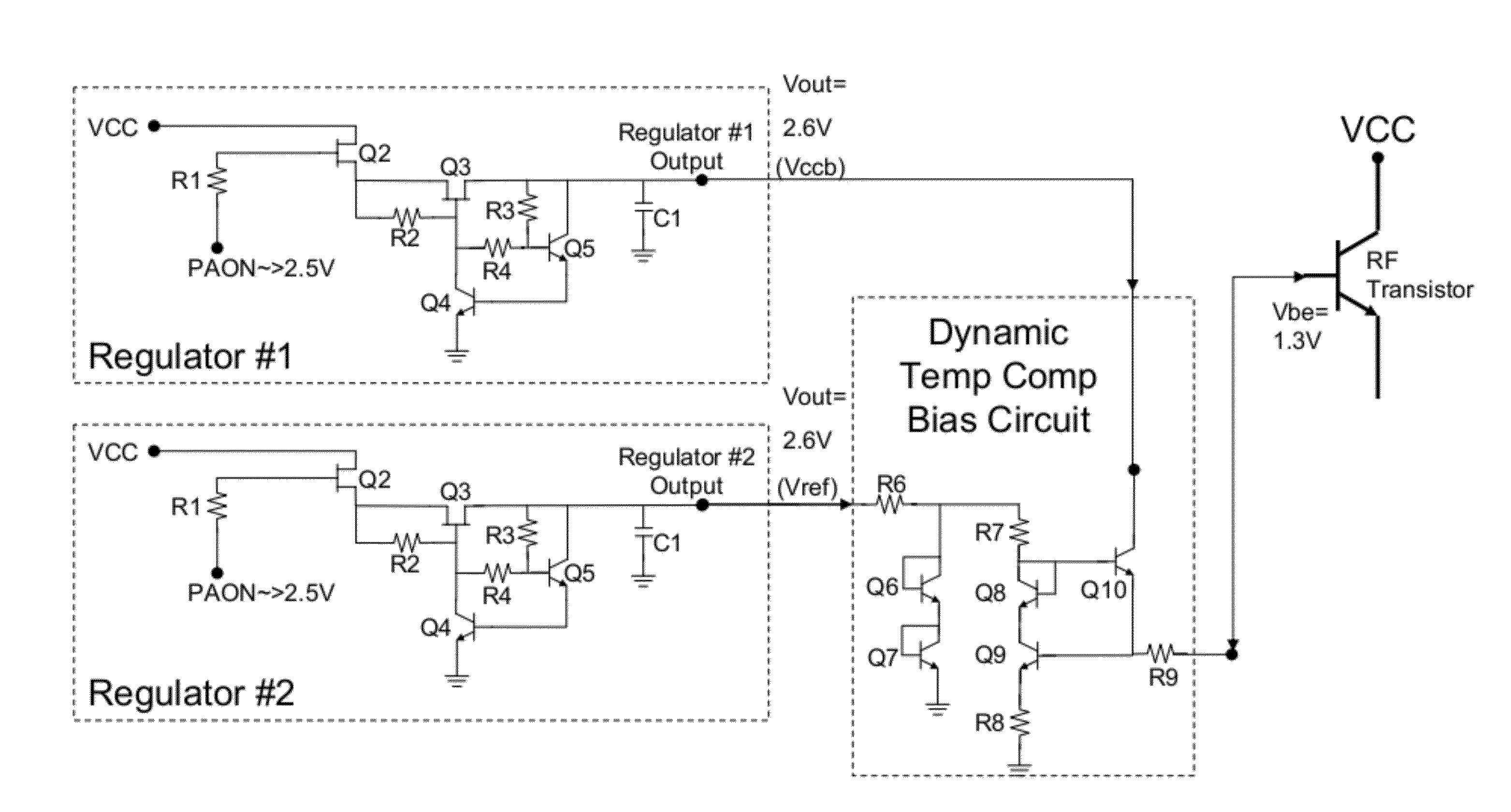
[0085]Through this paper, Vcc refers to the supply voltage of the output RF transistor of the linearized power amplifier, and Icc refers to current through the output RF transistor of the linearized power amplifier, in the case of a single stage of the amplifier. In a multi-stage amplifier, Vcc refers to the supply voltage of all of the RF transistors, and Icc refers to the total current through all of the RF transistors. Vcc is also the supply voltage for the regulator circuit, although a different supply voltage may be used.

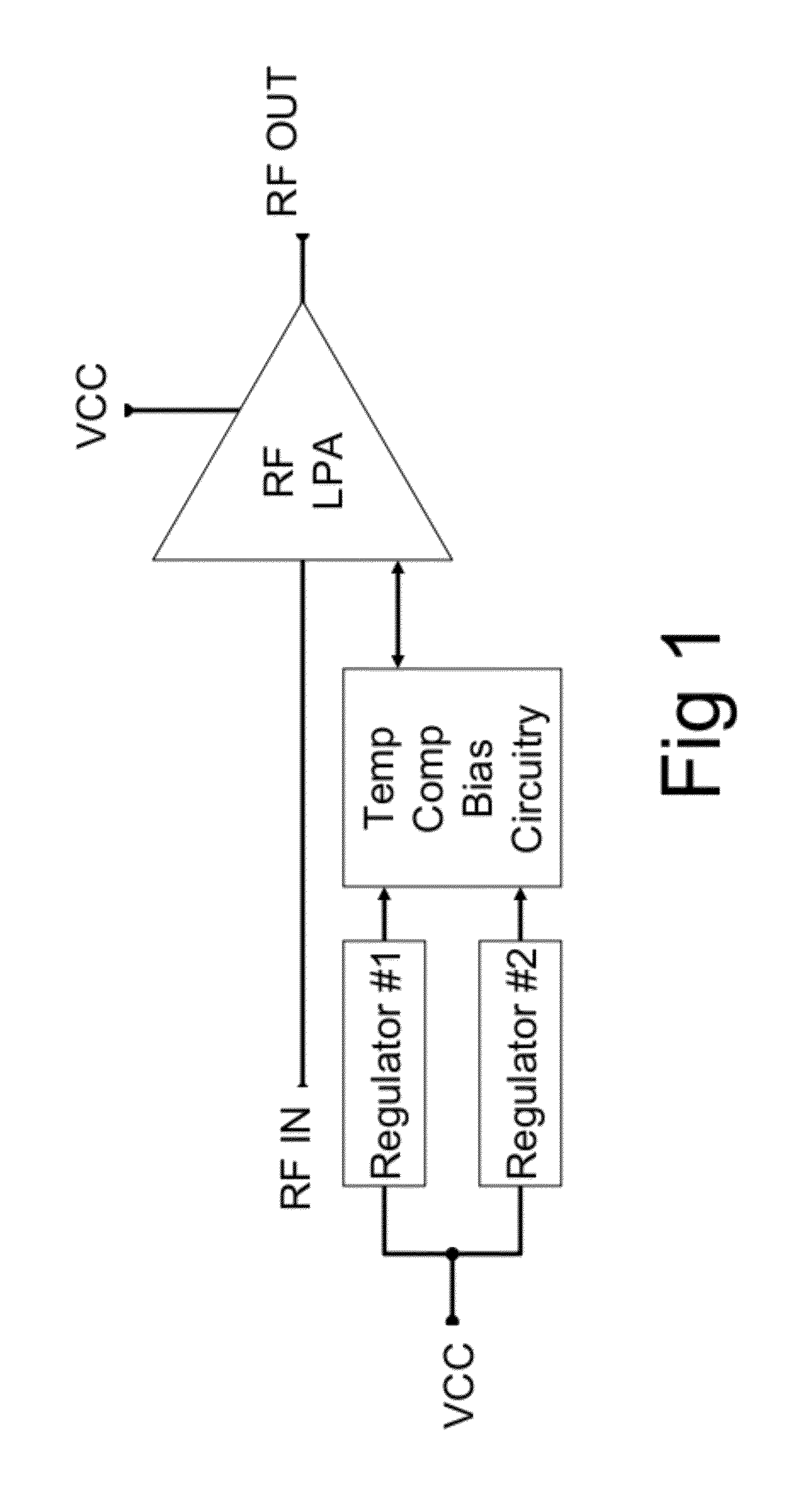
[0086]A power amplifier is a device that increases the power of an input signal by some ratio. The ratio of output power to input power is known as gain. Amplifiers amplify a signal within a certain frequency range, and the range of frequencies for which the amplifier provides useful gain (“useful gain” depending on the application) is known as the bandwidth. In addition to gain and output Power, other figures of merit for amplifiers include linearity and effic...


PUM


Abstract

An improved regulator circuit, temperature compensation bias circuit, and amplifier circuit are disclosed.

Description

REFERENCE TO RELATED APPLICATION[0001]This application claims the benefit of U.S. Provisional Application 61 / 217,963 filed 5 Jun. 2009, and claims the benefit of U.S. Provisional Application 61 / 281,635 filed 20 Nov. 2009, all of which are incorporated herein by reference.RELATED APPLICATION[0002]This application is related to U.S. patent application Ser. No. 11 / 664,749, which is incorporated herein by reference.BACKGROUND[0003]1. Field of the Invention[0004]This technology relates to linearized power amplifiers (LPAs).[0005]2. Description of Related Art[0006]Prior LPAs have a variety of issues as follows.[0007]1. Prior LPA Efficiency and Linearity Issues:[0008]Prior linearized power amplifiers have several deficiencies including less than optimal efficiency, linearity, and performance over a voltage range and over a temperature range. One of the primary goals of any LPA is to provide a linear signal at as high a power level as possible. In a prior art LPA, the LPA current increases ...

Claims


Application Information

Patent Timeline
IPC IPC(8): H03F3/04
CPCG05F1/56H03F1/302H03F1/32H03F3/195H03F2200/18H03F2200/447
Inventor YUEN, CINDYCHU, DUCLAURSEN, KIRK
Owner AMECO TECH HONG KONG LTD
Why Eureka
Try Eureka