
Sound definition language method with inline modifiers

a sound definition and inline modifier technology, applied in the field of electronic sound generation and control systems, can solve the problems that prior art does not encourage or in fact even allow the end user access to the core of sound-sequencing algorithms

Active Publication Date: 2012-07-24
IRELAND ANTHONY JOHN
View PDF8 Cites 7 Cited by
  • Summary
  • Abstract
  • Description
  • Claims
  • Application Information

AI Technical Summary

Benefits of technology

[0033]A further improvement over the prior art is to also allow the sound sequencer control file or SDF to contain more than one scheme that may then be user selected at any time during operation. This provides the capability of a significant and user defined adjustability to be executed.
[0065]This has a twofold benefit. It ensures only an authorized and proper device may be able to use this IPL and ensures an unambiguous verification of the IPL contents because known predefined data signature sections are embedded in the cipher-text portions and the authorization to accept (or alternately to spoof) the IPL is not corruptible, and it ensures that the IPL code may be disseminated from e.g. a web-site without compromising a manufacturers intellectual property and product development investment. Part of the IPL process set up can include clear text or even human recognizable data as the first stage of validation, but an encrypted validation phase in vital to ensure decoder integrity and safety. For security, only the manufacturer and secure portions of the decoder boot-loader need know the unique encryption key to be used for any product IPL. The validation by these additional steps does not mean that the communication links carrying the data from the original source such as a web site or a data file from a file storage device do not also include any of the numerous well-known data integrity verification means to ensure quality of data transfer in each step of the data downloading process.

Problems solved by technology

The prior art does not encourage or in fact even allow the end user access to the core of the sound-sequencing algorithms.

Method used


Image

  • Sound definition language method with inline modifiers
  • Sound definition language method with inline modifiers
  • Sound definition language method with inline modifiers

Examples


Embodiment Construction

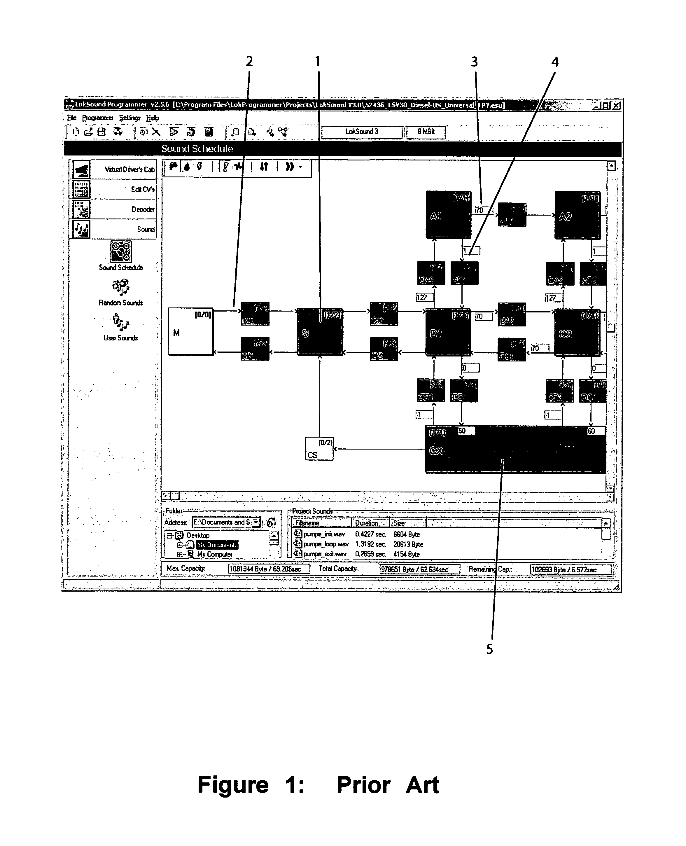
[0078]FIG. 1 depicts a configuration screen from a prior art ESU version 2.5.6 programmer software running under the Windows operating system and used for downloading and configuring their proprietary LokSound sound decoders. Item 1 represents the locomotive stationary or idle state when the “sound schedule” or sound scheme editing capability is selected. The balance of small boxes in the main software window of FIG. 1 represent a number of other speed states that are part of a state-machine sound scheme that may be set up by the user to define sounds to playback at each decoder state. Item 2 indicates a state transition from a mute (M) state to muted-stationary state (MS), and the arrow indicates the direction and reason for the state change.

[0079]The example selected is an ESU sound project “Universal FP7” diesel scheme with three major state changes in the prime mover speed states. The prime mover sounds such as the diesel engine or steam exhaust chuff sounds are usually the most...


PUM


Abstract

A method and apparatus is shown to provide a downloadable and user configurable sound generator based on a Sound Definition Language method with inline modifiers, which provides the maximum user customization, flexibility and adjustment of sounds that can be produced. The embodiments of this method allow the creation of sound decoders that may be securely downloaded with sound and IPL data and that will operate in power limited environments with resistance to power drop outs and are significant improvements beyond prior art devices.

Description

[0001]This disclosure contains material that is copyrighted and for which all rights are reserved. This copyrighted material may not be used for commercial purposes without written permission of the copyright holder, but may be used as required for the prosecution of this application by the Patent and Trademark Office.FIELD OF THE INVENTION[0002]This invention pertains to the field of electronic sound generation and control systems for model railroad layouts, and specifically to expanding the control of layout sound effects generators that are configurable and customizable by end users.BACKGROUND OF INVENTION[0003]The advent of Command Control technologies based on digital control signals has led to increased enjoyment and capabilities for model railroaders and their operations of model railroad layouts. Control technologies such as the widely used National Model Railroad Association Digital Command Control Standard (NMRA DCC) and others provide a rich set of control possibilities i...

Claims


Application Information

Patent Timeline
IPC IPC(8): G06F17/00B61L5/20
CPCA63H19/00A63H19/14A63H19/24
Inventor IRELAND, ANTHONY JOHN
Owner IRELAND ANTHONY JOHN
Learn More