
Torque balancing gearbox

a gearbox and torque balancing technology, applied in the direction of gearbox, vertical landing/take-off aircraft, transportation and packaging, etc., can solve the problems of extremely heavy planet-based gearbox systems and thus impractical for aircraft applications, and achieve the effect of reducing the power-to-weight ratio

Active Publication Date: 2012-07-31
KAREM AIRCRAFT INC
View PDF11 Cites 15 Cited by
  • Summary
  • Abstract
  • Description
  • Claims
  • Application Information

AI Technical Summary

Benefits of technology

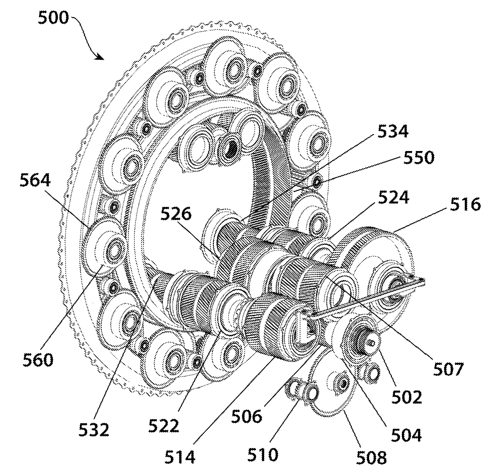
[0010]Such a preferred configuration could advantageously allow for the placement of at least 6, 10, 20, 30 or 50 planet gears that mate with the first row of helical teeth as well as at least 6, 10, 20, 30 or 50 planet gears that mate with the second row of helical teeth. It is contemplated that these planet gears could further be placed in a countershaft arrangement whereby some face forward and some face aft, thereby distributing load more evenly and allowing for the geometric fit of more planet gears.

Problems solved by technology

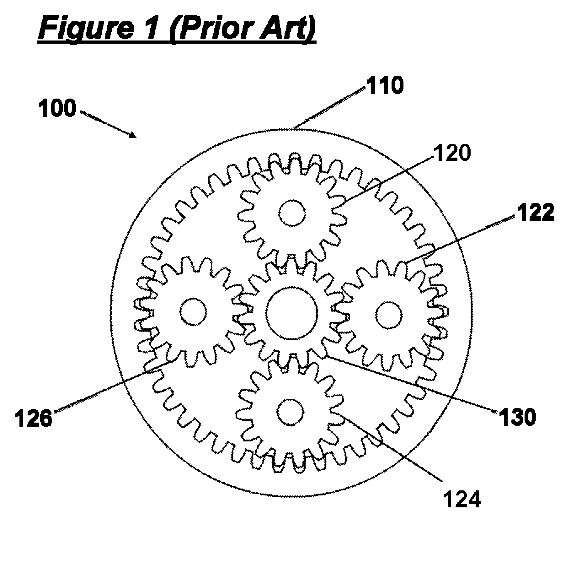
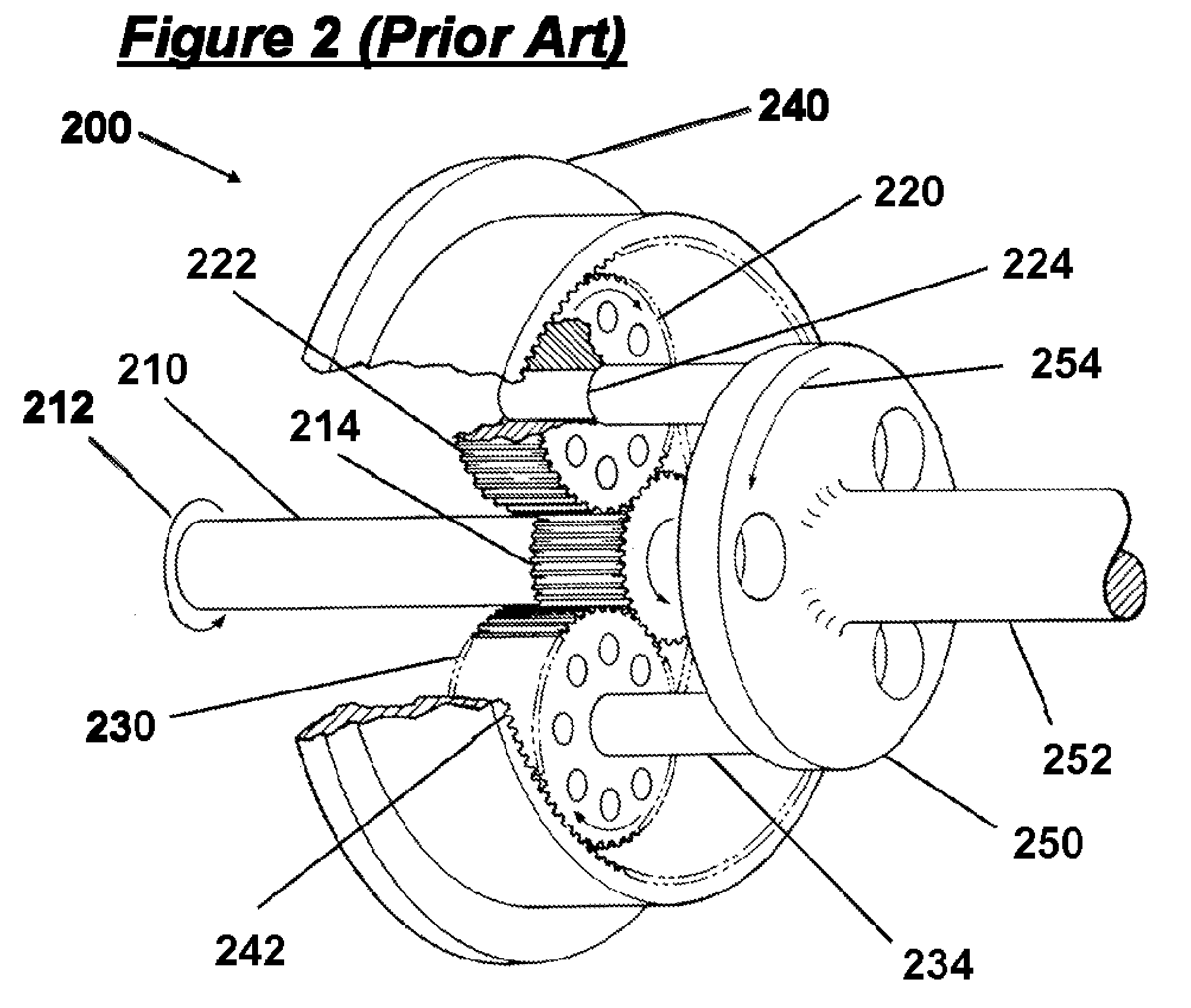
However, with propeller drives for aircraft or rotor drives for helicopters, weight and efficiency of the gearbox are critically important.
Such prior art planetary gearbox systems tend to become extremely heavy and thus impractical for aircraft applications when scaled to sizes commensurate with large transport aircraft.

Method used


Image

  • Torque balancing gearbox
  • Torque balancing gearbox
  • Torque balancing gearbox

Examples


Embodiment Construction

[0023]FIG. 3 is a schematic top view illustration of a preferred tiltrotor aircraft 300. The aircraft comprises a fuselage 302, wing 304, first rotor system 310, and second rotor system 320. The second rotor system 320 is shown in a vertical orientation, consistent with helicopter-mode flight. The first rotor system 310 is shown in a horizontal orientation, consistent with airplane-mode cruise flight. In practice, the first rotor system 310 and second rotor system 320 are likely to have a substantially similar orientation at any given time in flight.

[0024]A rotor system 310 comprises a hub 314 coupled to a tilting nacelle 312, which tilts with respect to the wing 304. A rotor blade 316 is coupled to the rotor hub 314. An engine 350 is preferably disposed within the tilting nacelle 312 and is coupled to a shifting gearbox 370. The shifting gearbox is coupled to a numerical reduction ratio reduction gearbox 180. The reduction gearbox 380 is coupled to and drives the rotor hub 314. A m...


PUM


Abstract

A gearbox comprising a gearset is able to transmit high output torques at high numerical reduction ratios at a power-to-weight ratio higher than previously attainable with existing designs. A distributor gear is disposed relative to a spur gear in order to produce automatic torque balancing. The distributor gear can be advantageously configured as an input floatring gear, for which support in all directions is provided by gear tooth mesh forces rather than bearings. Automatic torque balancing is achieved by configuring the distributor gear with first and second rows of helical teeth on the external circumference, and with a set of double helical teeth disposed on the internal circumference of the distributor gear. This allows for the placement of up to 50 or more planet gears in a countershaft arrangement with one end having helical teeth and the other end having spur teeth.

Description

[0001]This application claims priority to U.S. provisional application Ser. No. 61 / 034,462, filed Mar. 6, 2008, the disclosure of which is incorporated herein by reference in its entirety.FIELD OF THE INVENTION[0002]The field of the invention relates to the transmission of power by gears.BACKGROUND[0003]When gas turbine or turboshaft engines are employed to drive a plant, machinery, or a vehicle, a high numerical reduction ratio is frequently required because of the high output speed (often measured in rotations per minute or rpm) of the turbine. Power transmission of several thousands of horsepower is encountered in many applications. In the case of a stationary plant, or in marine applications, mechanical reliability can be readily achieved if the weight of the gearbox is not critically important. However, with propeller drives for aircraft or rotor drives for helicopters, weight and efficiency of the gearbox are critically important. This requirement led to the widespread adoptio...

Claims


Application Information

Patent Timeline
Patent Type & Authority Patents(United States)
IPC IPC(8): F16H57/08
CPCB64C29/0033B64D35/00F16H1/227
Inventor BUELNA, TERRY
Owner KAREM AIRCRAFT INC
Learn More