Check patentability & draft patents in minutes with Patsnap Eureka AI!

Automatic power control (APC) loop for adjusting the bias current of a laser diode

a technology of laser diodes and power control loops, which is applied in the direction of electrical apparatus, laser details, semiconductor lasers, etc., can solve the problems of circuit complexity and increase the power consumption of the comparator b>14/b>

Inactive Publication Date: 2012-08-07
TM TECHNOLOGY INC
View PDF2 Cites 2 Cited by
  • Summary
  • Abstract
  • Description
  • Claims
  • Application Information

AI Technical Summary

Benefits of technology

"The present invention provides an automatic power control loop for adjusting the bias current of a laser diode. The loop includes a laser diode, a photo diode, a controller, a switch selector, a transducer, a comparator, a counter, and a laser diode driver. The controller receives a control signal and selects a predetermined current among a plurality of switches connected to the controller. The selected predetermined current is connected to the laser diode through the switch. The transducer receives a current difference between the feedback current and the selected predetermined current and generates a comparison signal. The comparator compares the load voltage with a reference voltage and generates a comparison signal. The counter records and counts the comparison signal and the control signal. The laser diode driver receives the count value and generates the bias current for the laser diode. The technical effect of this invention is to provide a stable and automatic power control loop for adjusting the bias current of a laser diode, which ensures a constant light intensity output."

Problems solved by technology

In such a way, the circuit complexity and power consumption of the comparator 14 will increase because of the complicated comparative procedure, which is unfavorable for the circuit development and circuit application of the automatic power control loop 100.

Method used


Image

  • Automatic power control (APC) loop for adjusting the bias current of a laser diode
  • Automatic power control (APC) loop for adjusting the bias current of a laser diode
  • Automatic power control (APC) loop for adjusting the bias current of a laser diode

Examples


Embodiment Construction

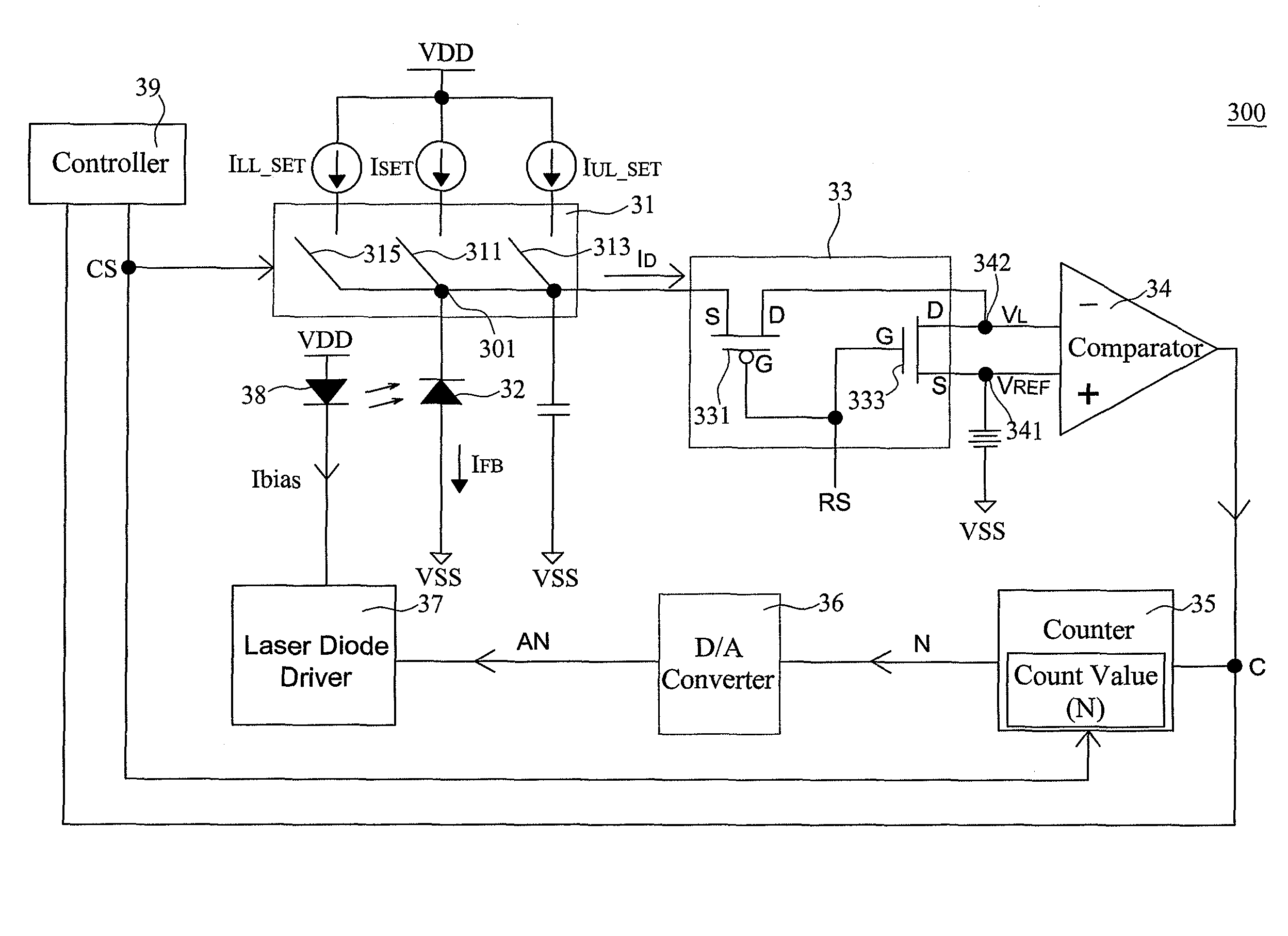
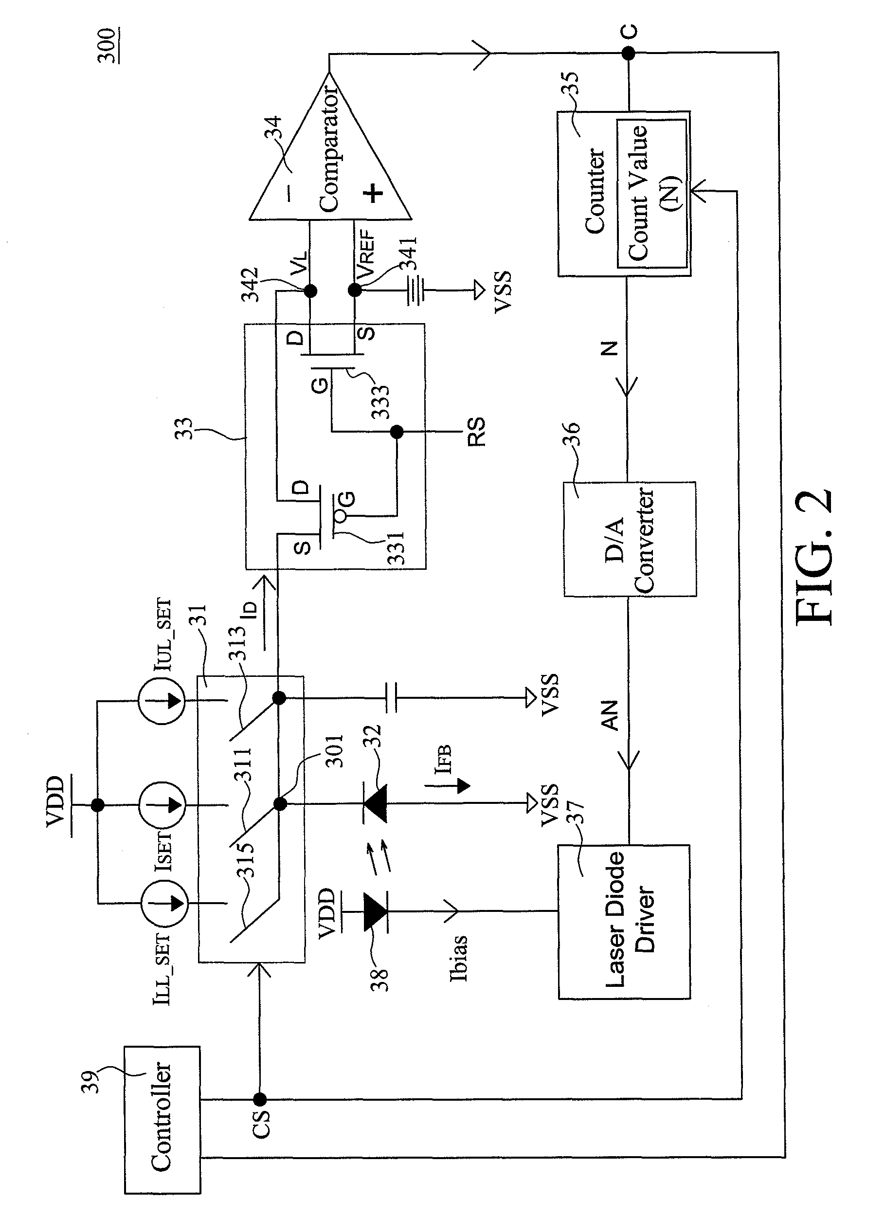
[0021]Referring to FIG. 2, there is shown a circuit structure diagram for the automatic power control loop according to a preferred embodiment of the present invention. The present invention provides an automatic power control loop 300 that will be applied to adjust the light intensity of the light signal in a burst mode optical communication system. As shown in FIG. 2, the automatic power control loop 300 comprises a switch selector 31, a photo diode 32, a transducer 33, a comparator 34, a counter 35, a laser diode driver 37, a laser diode 38, and a controller 39.

[0022]Wherein, the laser diode 38 functioning as a light source in the optical communication system is operated by receiving a bias current (Ibias). The photo diode 32 is used for sensing the light intensity of the laser diode 38 to generate a feedback current (IFB) equal to the bias current (Ibias), and is connected to a first node 301. The first node 301 is the connection point between the photo diode 32 and the switch s...


PUM


Abstract

A automatic power control loop comprises a photo diode used for sensing a light intensity of a laser diode to generate a feedback current, a switch selector used for selecting one among a plurality of predetermined currents according to a control signal generated by a controller, a transducer used for transferring a current different between the feedback current and the selected predetermined current into a load voltage, a comparator used for comparing the load voltage with a reference voltage to generate a comparison signal, a counter used for counting a count value according to the comparison signal and the control signal, and a laser diode driver used for generating a corresponding bias current in response to the count value to drive the laser diode. Thereby, the bias current will be adjusted within an allowable range, so that the light source of the laser diode can maintain a constant light intensity.

Description

FIELD OF THE INVENTION[0001]The present invention is related to an automatic power control loop for adjusting the bias current of a laser diode, where the feedback of the bias current used for operating the laser diode will be adjusted to an allowable range, so that the light source of the laser diode can maintain a constant light intensity.BACKGROUND OF THE INVENTION[0002]Common burst mode optical communication systems for conducting data communication through transmission of light signals by means of optical fibers are provided with a digital automatic power control loop (digital APC loop) that maintains a constant output light intensity of a light source. In said optical communication systems, it is commonplace to use a laser diode as the light source. The digital automatic power control loop is used for monitoring the output light source of the laser diode to adjust the bias current of the laser diode to a predetermined current value, such that the output light source of the las...

Claims


Application Information

Patent Timeline
Patent Type & Authority Patents(United States)
IPC IPC(8): H01S3/00
CPCH01S5/0683H01S5/042
Inventor WANG, CHIH-YANGWANG, CHI-PING
Owner TM TECHNOLOGY INC
Features
  • R&D
  • Intellectual Property
  • Life Sciences
  • Materials
  • Tech Scout
  • Unparalleled Data Quality
  • Higher Quality Content
  • 60% Fewer Hallucinations
Learn More