Hydraulic brake booster

Active Publication Date: 2012-08-14
ROBERT BOSCH CORP +1
View PDF19 Cites 19 Cited by
  • Summary
  • Abstract
  • Description
  • Claims
  • Application Information

AI Technical Summary

Benefits of technology

[0010]An advantage of the present invention is that many features of conventional braking systems are retained. The reaction force and gain principle are essentially the same as in a conventional actuation system. There is the same failed boost performance as conventional actuation system. An active boost function is available to support pressure build during an ESP event and the system can be used as an actuator for regenerative brake systems (RBS). A high flow master cylinder is not required. In one form, the system is interchange

Problems solved by technology

There is the same failed boost perform

Method used


Image

  • Hydraulic brake booster
  • Hydraulic brake booster
  • Hydraulic brake booster

Examples


Embodiment Construction

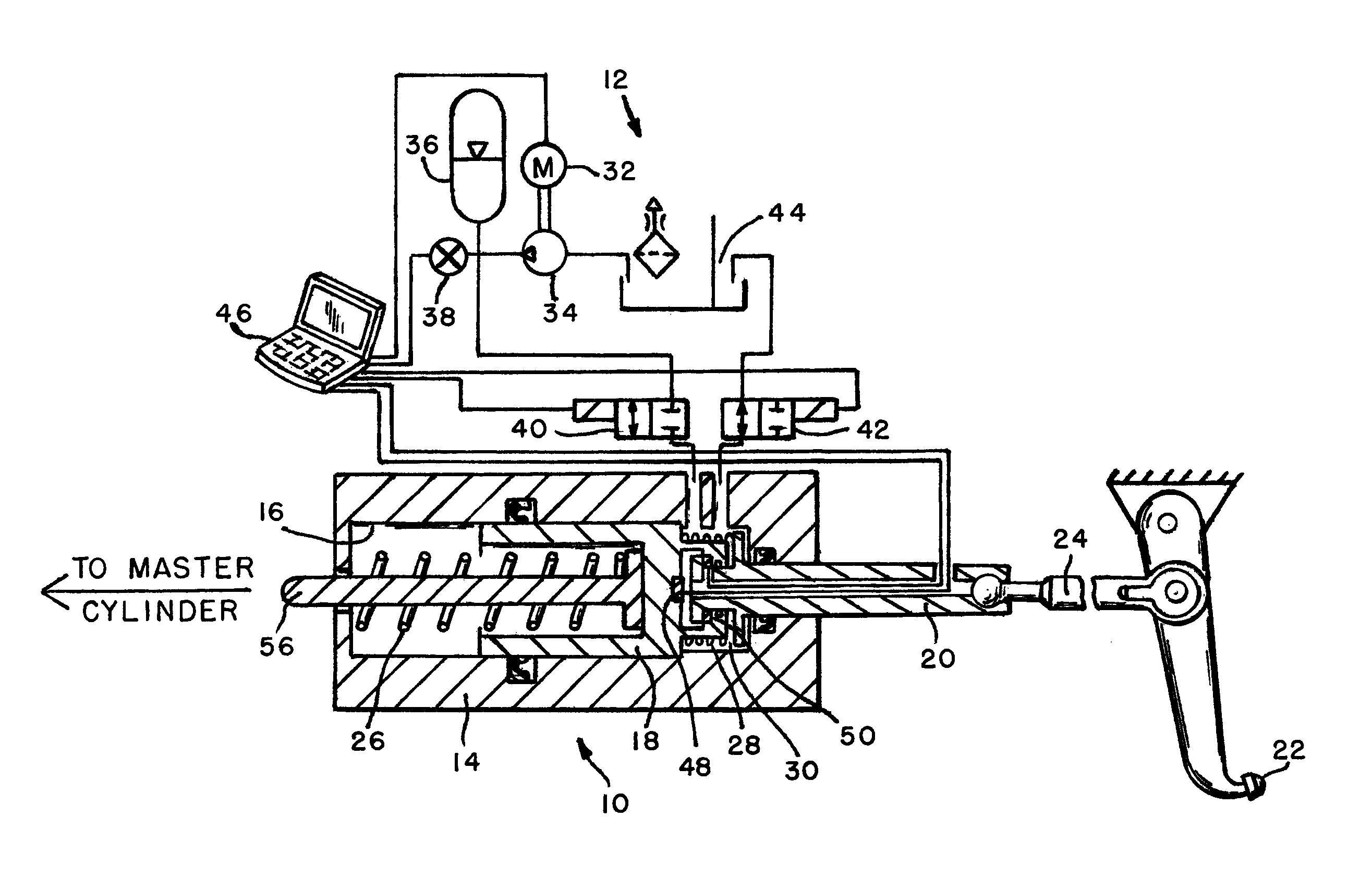
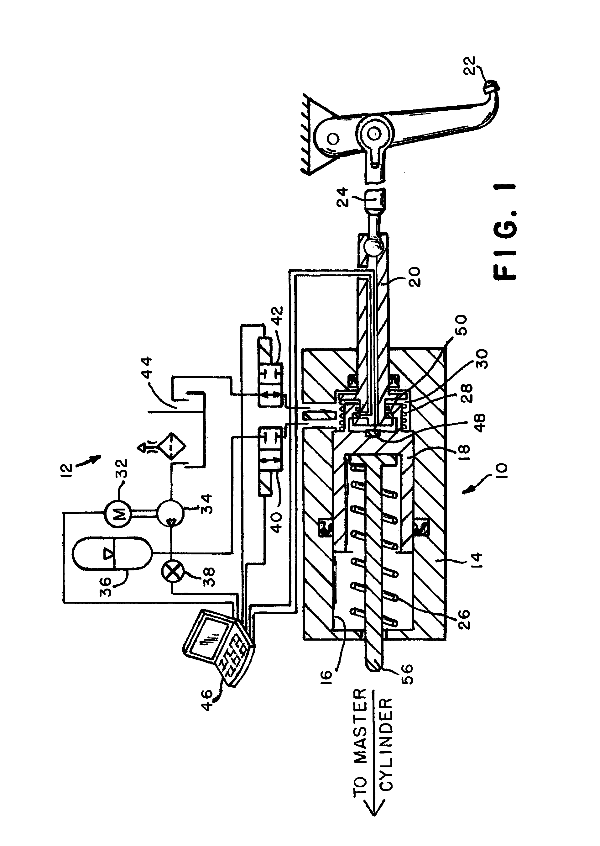
[0020]Referring now to the drawings and particularly to FIG. 1, there is shown a hydraulic power boost unit 10 and a boost fluid pressure source such as energy unit 12. The boost unit or booster 10 includes a housing 14 having a cylindrical bore 16 with a boost piston 18 reciprocably disposed therein. An input member or rod 20 is coupled to an operator brake pedal 22 by a linkage 24 and is responsive to an operator pedal input to supply pressure fluid to individual wheel brake actuators such as illustrated in FIGS. 4 and 5. In an event that the boost unit 12 is inoperative, input member 20 moves piston 18 within bore 16 to provide an output member 56 with a force that is transmitted to a conventional master cylinder in much the same way as a vacuum failure mode in a brake system having a conventional vacuum booster. The cylindrical bore 16 retains a boost piston return spring 26, a cut in spring 28, and in conjunction with piston 18. Piston 18 is positioned within bore 16 to define ...


PUM


Abstract

A supply valve (40), a relief valve (42) and a microprocessor (46) control the supply of pressurized hydraulic fluid from a dedicated pressure source (12) to a brake boost piston (18, 60, 108) interposed between an operator brake pedal (22) input member (20, 106) and a master cylinder. Transducers (48, 50, 102) sense a current relationship between the input member (20, 106) and the boost piston (18, 60, 108) and supply the microprocessor (46) with a input to accordingly operate the supply valve (40) and relief valve (42). In one embodiment, a single transducer (102) senses relative motion between the input member and the piston while in a second embodiment, a single transducer (48) senses the force exerted on the piston by the input member and a third embodiment first and second transducers (48, 50) to sense relative motion between the input member and the piston.

Description

BACKGROUND OF THE INVENTION[0001]1. Field of the Invention[0002]The present invention relates to a brake booster system and more particularly to an improved technique for controlling hydraulic boost in response to vehicle operator pedal input.[0003]2. Description of the Related Art[0004]Vehicle braking systems have evolved from simple mechanical brakes to hydraulic brakes and then to power assisted braking systems to reduce a driver's brake pedal effort. Many power assisted braking systems rely on the manifold vacuum created by the engine pistons as they draw air into the engine. A common power brake mechanism such as disclosed on U.S. Pat. No. 5,943,863 employs a housing that is intermediate an operator brake actuating pedal mechanism and a master cylinder. When this brake mechanism is enabled, fluid pressure is supplied to individual wheel brake cylinders or actuators. The housing includes a piston or diaphragm normally exposed on both sides to vehicle manifold vacuum. When the op...

Claims


Application Information

Patent Timeline
IPC IPC(8): B60T8/44
CPCB60T8/3265B60T8/441B60T8/4872B60T13/147
Inventor KLIMES, MILAN
Owner ROBERT BOSCH CORP
Why Eureka
Try Eureka