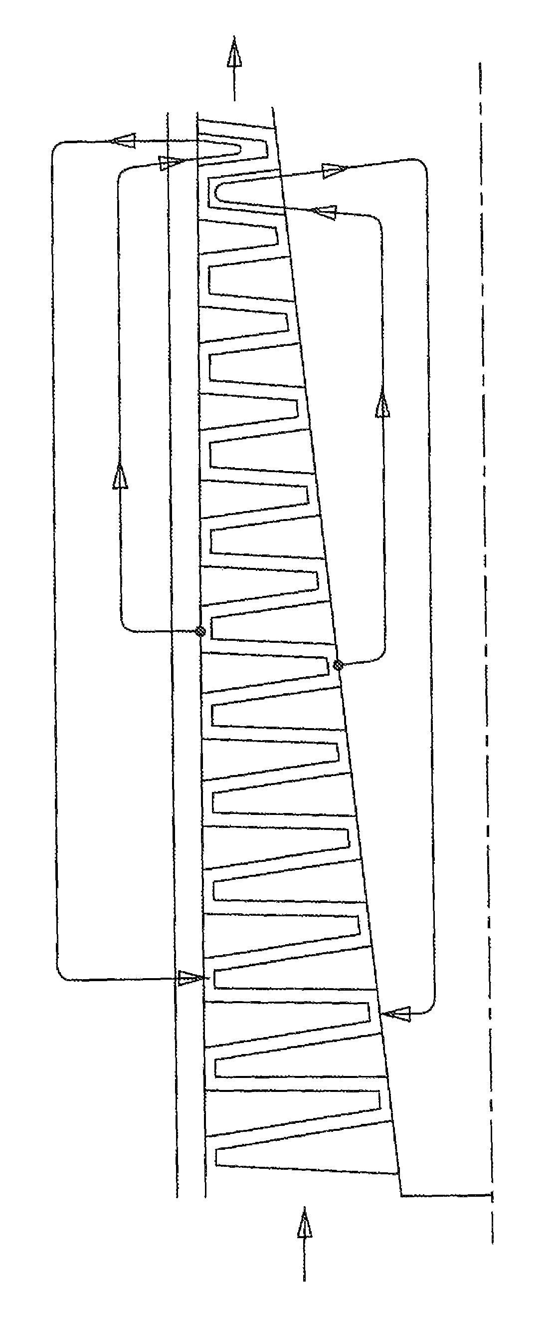
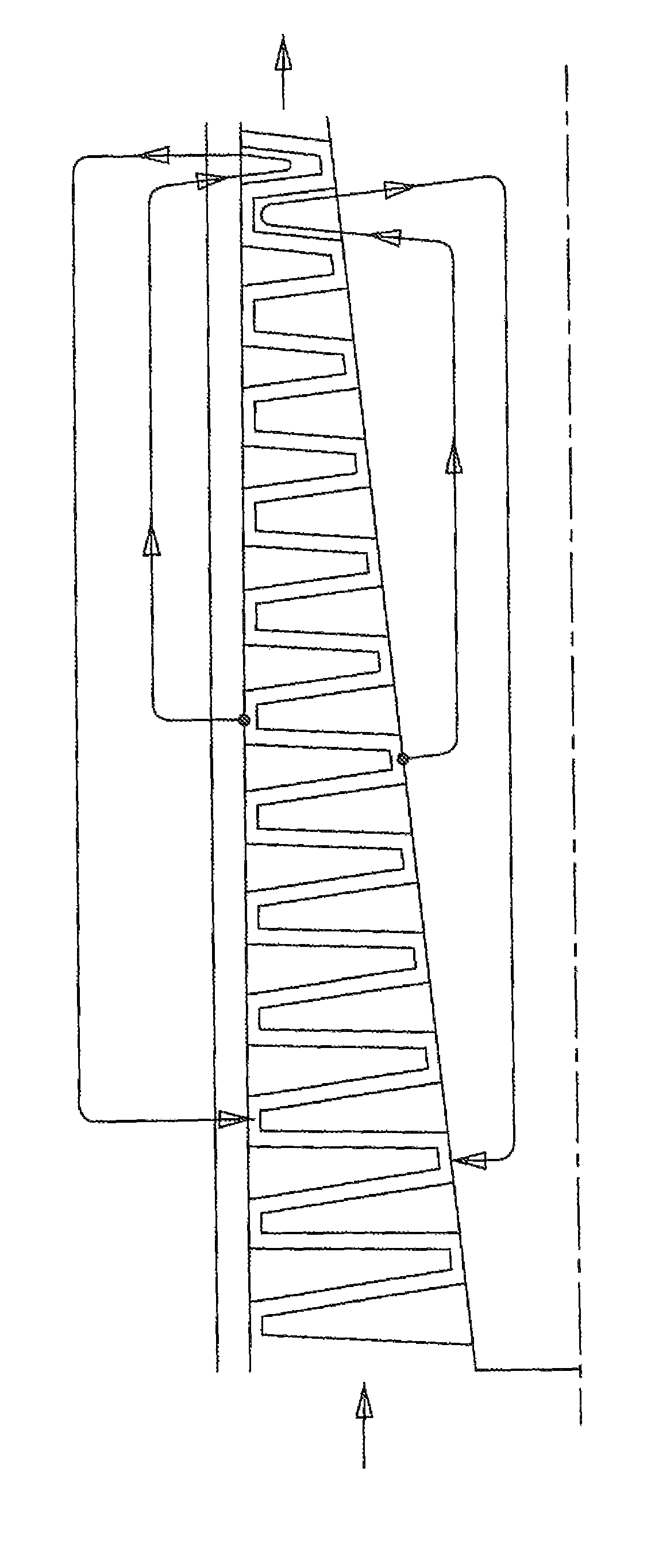
Multiple staged compressor with last stage airfoil cooling

a compressor and air foil technology, applied in the direction of liquid fuel engines, machines/engines, efficient propulsion technologies, etc., can solve the problem that the cooling air foil cannot include the cooling air of the discharging film for the exterior surface, and achieve the effect of high pressure ratio

Active Publication Date: 2012-08-14
FLORIDA TURBINE TECH
View PDF1 Cites 23 Cited by
  • Summary
  • Abstract
  • Description
  • Claims
  • Application Information

AI Technical Summary

Benefits of technology

[0007]It is an object of the present invention to provide for a multiple s...

Problems solved by technology

Because the air pressure used for the cooling of the last stage airfoils is less than the external air flow pressure around these cooled a...

Method used


Image

  • Multiple staged compressor with last stage airfoil cooling
  • Multiple staged compressor with last stage airfoil cooling

Examples


Embodiment Construction

[0012]The present invention is a multiple stage compressor that produces a very high pressure ratio such that cooling of the last stage or stages of the compressor air required. The compressor is intended to be used in a gas turbine engine such as an aero engine or an IGT engine. However, the present invention could be used in any turbomachine in which a multiple stage compressor is used that produces the high pressure ratio in which cooling of the last stage airfoils is required to prevent thermal damage.

[0013]FIG. 1 shows a cross section of the compressor of the present invention in which a number of stages are present with each stage having a stator or guide vane located upstream from an associated rotor blade. In a typical multiple stage compressor of an aero engine, the outer diameter of the compressor is about at a constant radial diameter while the inner diameter is conical shaped with a decreasing airfoil spanwise height in the downstream direction. The inlet air to the comp...


PUM


Abstract

A high compression ratio compressor having multiple stages of airfoils to produce the high pressure rations, where the last stage airfoils are cooled by passing cooling air through the airfoils without discharging film cooling air. The cooling air for the airfoils is bled off from an upstream stage of the compressor, passed through the airfoil to provide for the cooling, and then discharged back into the compressor at a stage upstream of where the bleed off air was extracted and where the pressure is lower. Because of the high pressure rations, the air temperature in the compressor is at such a high temperature that the last stage airfoils must be cooled to prevent thermal damage.

Description

BACKGROUND OF THE INVENTION[0001]1. Field of the Invention[0002]The present invention relates go gas turbine engines, and more specifically to a high pressure ratio compressor with last stage airfoil cooling used in a gas turbine engine.[0003]2. Description of the Related Art Including Information Disclosed Under 37 CFR 1.97 and 1.98[0004]A gas turbine engine, such as an aero engine used to power an aircraft or an industrial gas turbine engine used to produce electric power, is a very efficient power plant. The compressed air from a compressor is passed into a combustor where the air is burned with a fuel to produce a hot gas flow, the hot gas flow is then passed through a turbine to drive the rotor shaft connected to the compressor and, in the case of an aero engine produce thrust and / or drive the fan, or in the case of the IGT drive an electric generator to produce the electric power. In both cases, the efficiency of the engine can be increased by passing a higher temperature gas ...

Claims


Application Information

Patent Timeline
IPC IPC(8): F01D5/14F03B11/00F03D11/00F04D29/38
CPCF02C6/08F02C7/18F04D29/324F04D29/542F04D29/584F05D2260/205Y02T50/676Y02T50/60
Inventor RYZNIC, JOHN E
Owner FLORIDA TURBINE TECH
Why Eureka
Try Eureka