
Method for making flat and high-density cathode for use in electrochemical cells

a technology of electrochemical cells and cathodes, which is applied in the direction of non-aqueous electrolyte cells, cell components, sustainable manufacturing/processing, etc., can solve the problems of adversely reducing the cell's effective volumetric energy density, and achieve the effects of improving the planarity of the electrode, improving the performance of the electrochemical cell, and high rate capability

Active Publication Date: 2012-08-14
WILSON GREATBATCH LTD
View PDF18 Cites 2 Cited by
  • Summary
  • Abstract
  • Description
  • Claims
  • Application Information

AI Technical Summary

Benefits of technology

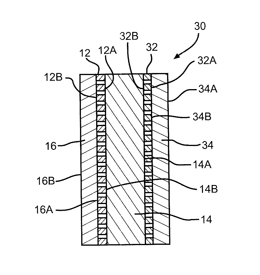
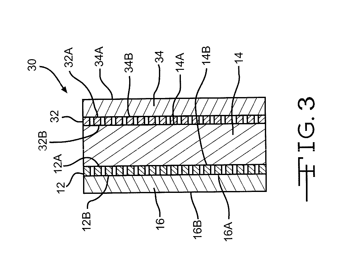
[0004]Accordingly, the object of the present invention is to improve the performance of an electrochemical cell, particularly a lithium electrochemical cell, by improving the planarity of an electrode having disparate active materials contacted to opposite sides of a current collector. Preferably, the electrode is a cathode comprising a first cathode active material of a relatively high rate capability, such as SVO, contacted to one side of the current collector with a second cathode active material of a relatively high energy density, such as CFx, contacted to the other side. In that manner, the separate SVO and CFx materials are short-circuited to each other through the perforated current collector. Providing the active materials in a short circuit relationship means that their respective attributes of high rate and high energy density benefit overall cell discharge performance.

Problems solved by technology

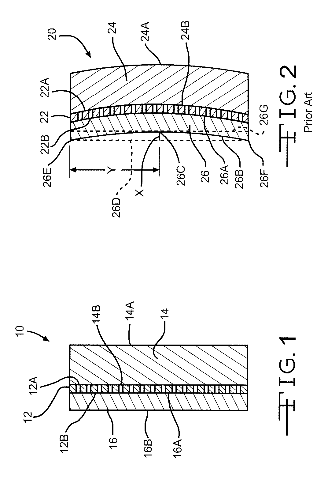
The problem is that contact pressing two disparate active materials onto opposite sides of a current collector by traditional methods often provides an electrode that is cupped.
This is undesirable as it results in there being different impedance at the electrode periphery where spacing with the counter anode material is relatively close in comparison to the center of the electrode where inter-electrode spacing is greater.
Cupping also adversely reduces the cell's effective volumetric energy density and frequently necessitates the addition of a remedial process step for flattening the electrode, which is not always successful.

Method used


Image

  • Method for making flat and high-density cathode for use in electrochemical cells
  • Method for making flat and high-density cathode for use in electrochemical cells
  • Method for making flat and high-density cathode for use in electrochemical cells

Examples


examples

[0039]In the traditional method, the CFx material is blanked at a pressure of about 0.24 tons / cm2 for about 20 seconds. The resulting CFx blank is then contacted to one side of a perforated current collector having an SVO blank contacted to the other side thereof. This assembly is then pressed together at about 4 tons / cm2 for about 10 seconds. The resulting cathode exhibits cupping of about 30% to about 60%.

[0040]According to the present method, the CFx material is blanked at 4.56 tons / cm2 for about 10 seconds. The resulting CFx blank is then contacted to one side of a perforated current collector having an SVO blank contacted to the other side thereof. This assembly is then subjected to a pressure of about 3.61 tons / cm2 for about 10 seconds. The present process resulted in cathodes that were less than 2% cupped. Additionally, the total process time has been reduced by 10 seconds from a total of 30 seconds for the conventional method to a total of about 20 seconds for the present pr...


PUM

PropertyMeasurementUnit
thicknessaaaaaaaaaa
weight percentaaaaaaaaaa

Abstract

The traditional method of pressing CFx, screen and SVO sheet assembly results in an electrode that is cupped and not flat. This results in the reduction of the effective volumetric energy density of the electrode or the addition of a process step of flattening of the cathode if at all possible. The new method of assembly effectively eliminates the cupping behavior and produces a flat electrode. In addition, the physical density of the cathode is also increased.

Description

BACKGROUND OF THE INVENTION[0001]This invention relates to the conversion of chemical energy to electrical energy. In particular, the present invention relates to an electrode for a lithium electrochemical cell. The electrode comprises a first cathode active material of a relatively low energy density but of a relatively high rate capability and a second active material having a relatively high energy density but of a relatively low rate capability. The first and second active materials are short circuited to each other by contacting the opposite sides of at least one perforated current collector. Alternately, the electrode can comprise spaced apart first and second perforated current collectors, the second active material being at an intermediate position with the first active material contacting the opposite, and outer current collector sides.[0002]A preferred form of the cell has the electrode as a cathode connected to a terminal lead insulated from the casing serving as the nega...

Claims


Application Information

Patent Timeline
Patent Type & Authority Patents(United States)
IPC IPC(8): H01M4/02
CPCH01M4/043H01M4/08H01M4/131H01M4/133H01M4/1391H01M4/1393H01M4/485H01M4/5835H01M6/16H01M10/052H01M10/058H01M4/661H01M4/663H01M4/667Y02E60/122Y02E60/10Y02P70/50
Inventor SHAH, ASHISHRUBINO, ROBERT S.GAN, HONG
Owner WILSON GREATBATCH LTD
Learn More