
Method of making a hetero tunnel field effect transistor

a technology of hetero-tunnel field and transistor, applied in the direction of semiconductor devices, electrical equipment, basic electric elements, etc., can solve problems such as out diffusion, and achieve the effect of reducing drastic out-diffusion

Active Publication Date: 2012-08-14
INTERUNIVERSITAIR MICRO ELECTRONICS CENT (IMEC VZW)
View PDF16 Cites 6 Cited by
  • Summary
  • Abstract
  • Description
  • Claims
  • Application Information

AI Technical Summary

Benefits of technology

The present patent provides a method for making a tunnel field effect transistor (TFET) with a heterojunction that eliminates or reduces the out-diffusion of dopants from the source region into the channel region, thereby improving the performance of the TFET. The method involves providing a substrate, depositing a drain region, depositing a channel region, and depositing a source region. A transition layer is used to prevent out-diffusion of the dopants. The method also includes selectively doping the source and drain regions to a desired level with a desired dopant type. The semiconductor materials used in the TFET may be selected from groups IV, III / V, or II / VI materials. The method may also include providing a gate dielectric and a gate electrode. The technical effect of the present patent is to improve the performance of TFETs by eliminating or reducing out-diffusion of dopants and maximizing tunneling current.

Problems solved by technology

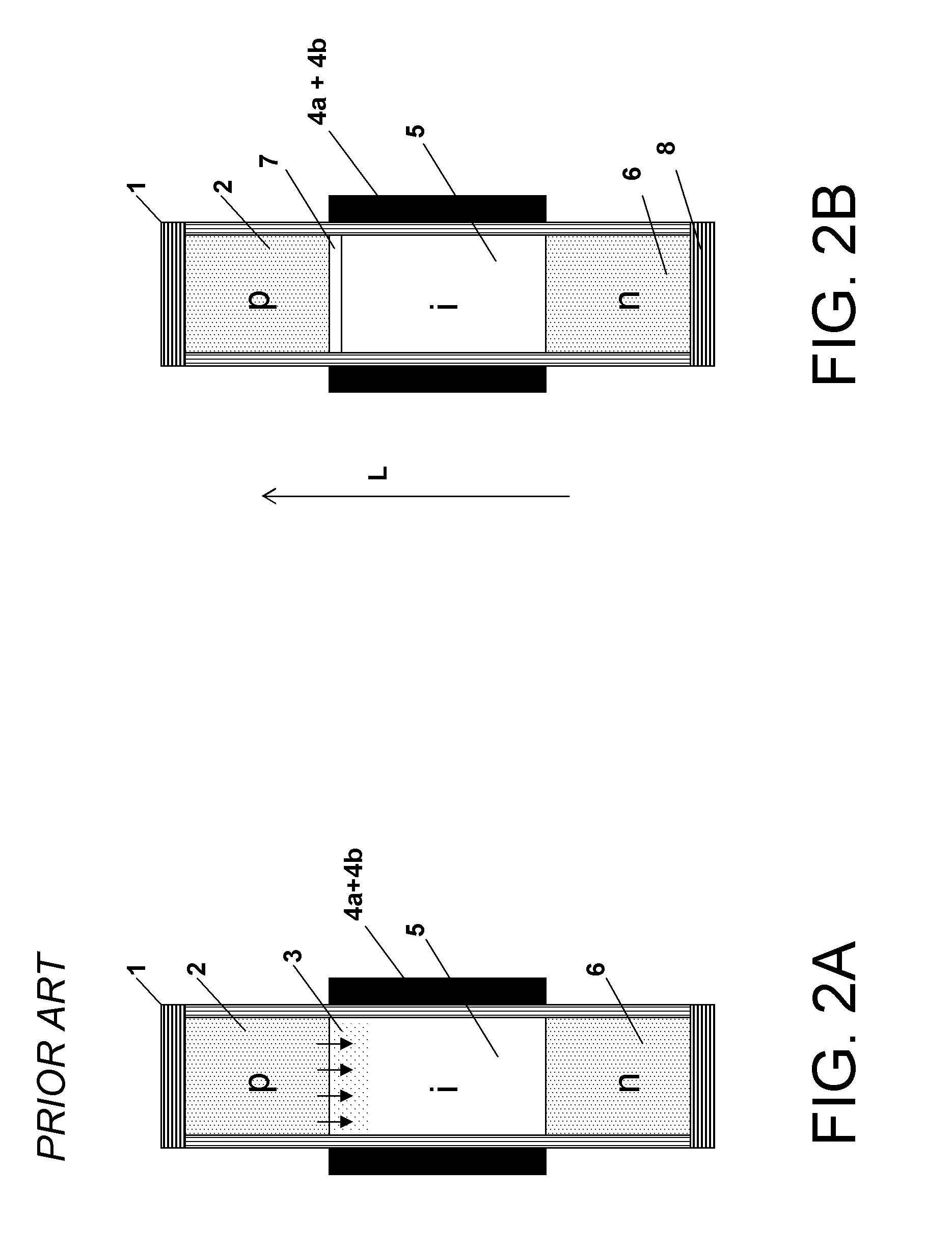
The problem of out diffusion especially occurs in heterostructures where the dopant of the source has lower diffusion kinetics in the channel material than in the source material.

Method used


Image

  • Method of making a hetero tunnel field effect transistor
  • Method of making a hetero tunnel field effect transistor
  • Method of making a hetero tunnel field effect transistor

Examples


Embodiment Construction

[0080]The present disclosure will be described with respect to particular embodiments and with reference to certain drawings but the disclosure is not limited thereto but only by the claims. The drawings described are only schematic and are non-limiting. In the drawings, the size of some of the elements may be exaggerated and not drawn on scale for illustrative purposes. The dimensions and the relative dimensions do not correspond to actual reductions to practice of the disclosure.

[0081]Moreover, the term top and the like in the description and the claims are used for descriptive purposes and not necessarily for describing relative positions. It is to be understood that the terms so used are interchangeable under appropriate circumstances and that the particular embodiments described herein are capable of operation in other orientations than described or illustrated herein.

[0082]It is to be noticed that the term “comprising”, used in the claims, should not be interpreted as being re...


PUM


Abstract

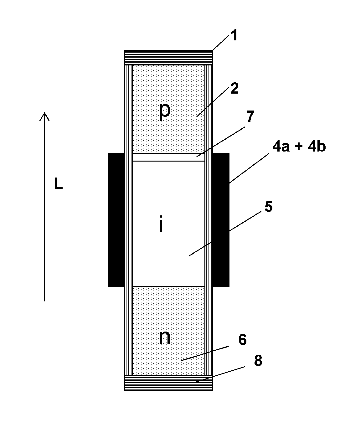
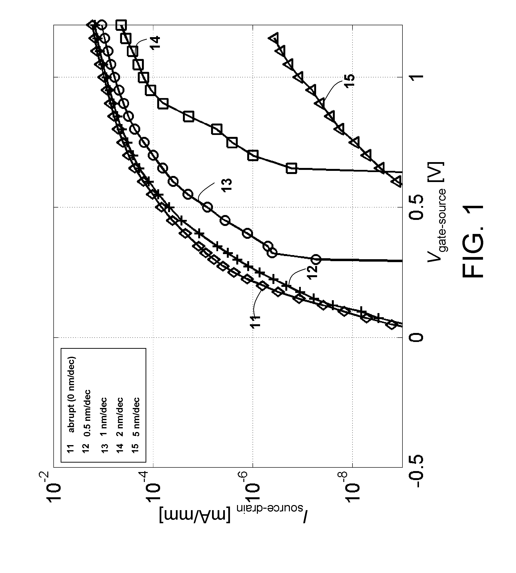
Embodiments of the present disclosure provide a method to fabricate a hetero-junction in a Tunnel Field Effect Transistor (TFET) device configuration (e.g. in a segmented nanowire TFET). Since in prior art devices the highly doped source is in direct contact with the lowly doped or undoped channel, some amount of dopants will diffuse from the source to the channel which cannot be avoided due to the source deposition thermal budget. This out-diffusion reduces the steepness of the doping profile and hence deteriorates the device operation. Particular embodiments comprise the insertion of a thin transition layer in between the source region and channel region such that the out-diffusion is within a very limited region of a few nm, guaranteeing extremely good doping abruptness thanks to the lower diffusion of the dopants in the transition layer. The transition layer avoids the direct contact between the highly doped (e.g. Ge or SiGe) source region and the lowly doped or undoped (e.g. Si) channel and allows to contain the whole doping (e.g. B atoms) entirely within the source region and transition layer. The thickness of the transition layer can be engineered such that the transition layer coincides with the steep transition step from the highly doped source region to the intrinsic region (channel), and hence maximizing the tunneling current.

Description

CROSS-REFERENCE TO RELATED APPLICATION[0001]This application claims the benefit under 35 U.S.C. §119(e) of U.S. provisional application Ser. No. 61 / 220,095, filed Jun. 24, 2009, the disclosure of which is hereby expressly incorporated by reference in its entirety and is hereby expressly made a portion of this application.FIELD OF THE INVENTION[0002]The present disclosure relates to the field of semiconductor devices and nanotechnology. More specifically, the disclosure relates to a nanostructure semiconductor device, more specifically to a tunnel field effect transistor having a segmented nanostructure (e.g. a heterostructure nanowire). Furthermore the disclosure relates to a method for manufacturing tunnel field effect transistor devices with integrated nanostructures such as nanowires having improved device properties.BACKGROUND OF THE INVENTION[0003]Microelectronic devices are generally fabricated on semiconductor substrates as integrated circuits. A complementary metal-oxide-sem...

Claims


Application Information

Patent Timeline
Patent Type & Authority Patents(United States)
IPC IPC(8): H01L21/336
CPCH01L29/7391H01L29/0676H01L29/161H01L29/165
Inventor IACOPI, FRANCESCAVERHULST, ANNE S.SIBAJA-HERNANDEZ, ARTURO
Owner INTERUNIVERSITAIR MICRO ELECTRONICS CENT (IMEC VZW)
Learn More