
Folded and spiral CFL bulb safety cups, diffusion covers and shade assemblies

a technology of diffusion cover and cfl bulb, which is applied in the direction of discharge tube main electrodes, vacuum tube vessels/containers/shields, lighting and heating apparatus, etc., can solve the problems of phosphor/mercury amalgam-coated glass shards, no means of proper pick-up, handling and disposal of broken glass, and exponential decay of light outpu

Inactive Publication Date: 2012-08-14
DIVERSIFIED ELECTRONICS
View PDF21 Cites 4 Cited by
  • Summary
  • Abstract
  • Description
  • Claims
  • Application Information

AI Technical Summary

Benefits of technology

"The invention is a screw-on or slip-on cover for spiral-tube or folded-tube fluorescent bulbs (CFLs) that can be used in various orientations. The covers are designed to securely retain the CFLs in place and prevent skin contact with the broken bulb shards. The covers can be made from a variety of thermosetting or thermoplastic plastics that are molded or machined to fit the CFL tubing without scratching or breaking the glass. The plastic can be transparent or translucent, and can be colored to match the decor of the room. The covers can be used for any type of CFL, including upright, downward, or angled CFLs. The covers provide a safe way to handle and install or remove CFLs, and can be designed with a wide range of shapes and textures."

Problems solved by technology

Although CFLs produce less light later in their lives than when they are new, the light output decay is exponential, with the fastest losses being soon after the lamp is first used.
While this coating accounts for the improved energy efficiency of CFLs, it seriously complicates their disposal, especially in cases where tubes are broken, as both are hazardous materials.
Current CFLs sold are in large percentage, bare bulbs, with no means of proper pick-up, handling and disposal of broken, phosphor / mercury amalgam-coated glass shards.
In addition, most people find the shape and folds of the folded-tube fluorescent bulbs to be unacceptable, if not downright ugly, from aesthetic and design viewpoints.
As a result, the bases are enlarged, and do not fit in many lamp sockets.
Accordingly, there remain a vast number of bare spiral and folded-tube bulbs in use that are not the preference of users and present a disposal and breakage hazard.
In addition, those covers cause light loss, requiring the consumer to use higher-wattage CFLs, thereby defeating the cost savings.
Indeed, in some cases users retain incandescent bulbs rather than use the spiral or folded-tube fluorescents because of light loss, design or aesthetic considerations.
It can be particularly objectionable as not providing warmth to skin tones.

Method used


Image

  • Folded and spiral CFL bulb safety cups, diffusion covers and shade assemblies
  • Folded and spiral CFL bulb safety cups, diffusion covers and shade assemblies
  • Folded and spiral CFL bulb safety cups, diffusion covers and shade assemblies

Examples


first embodiment

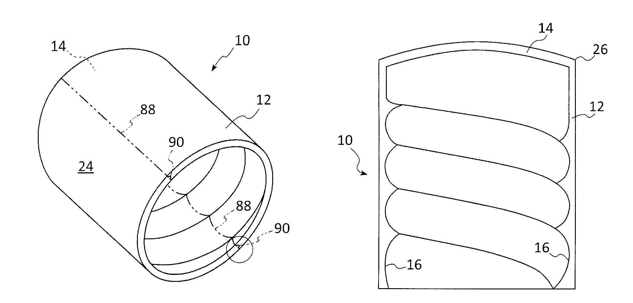
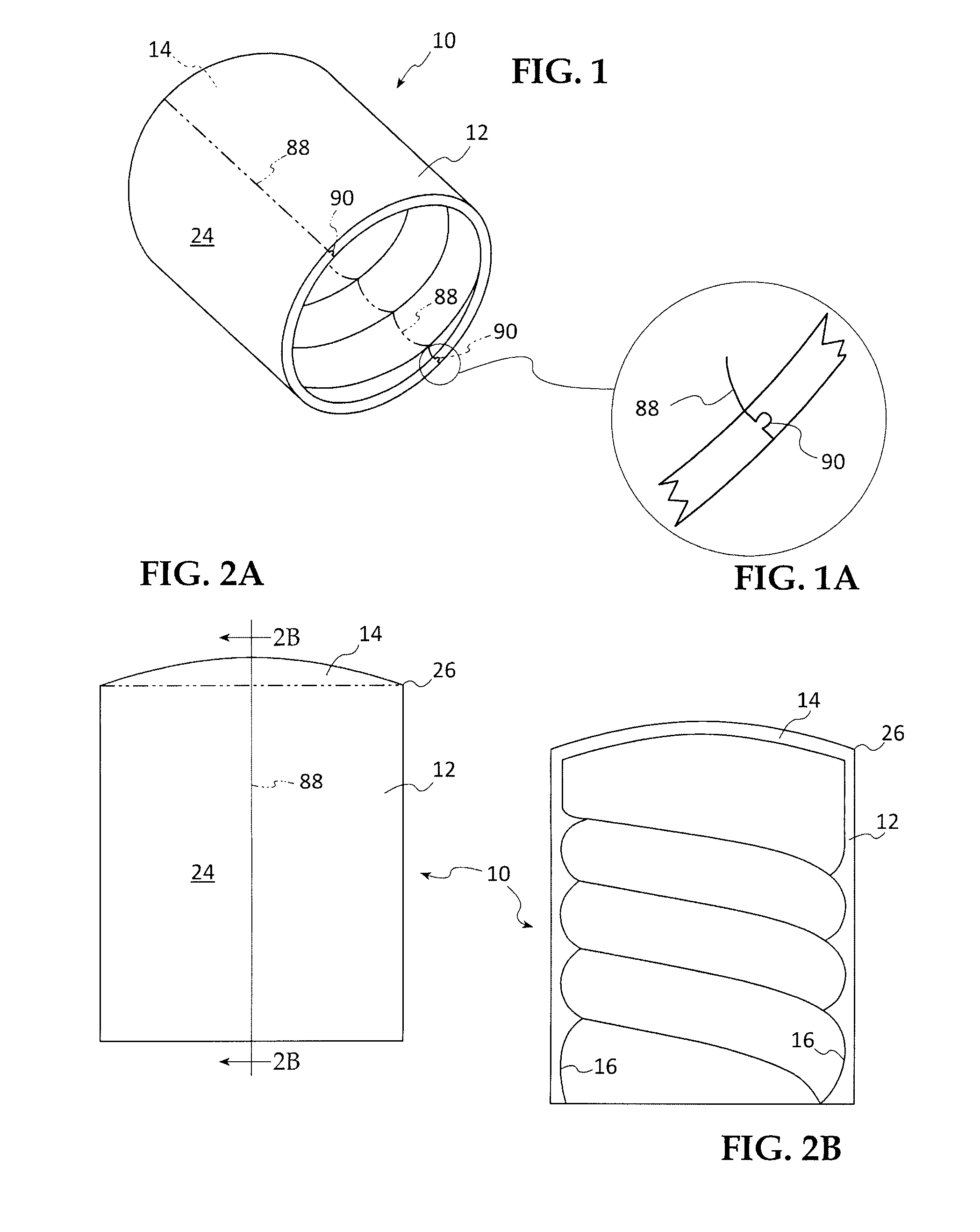
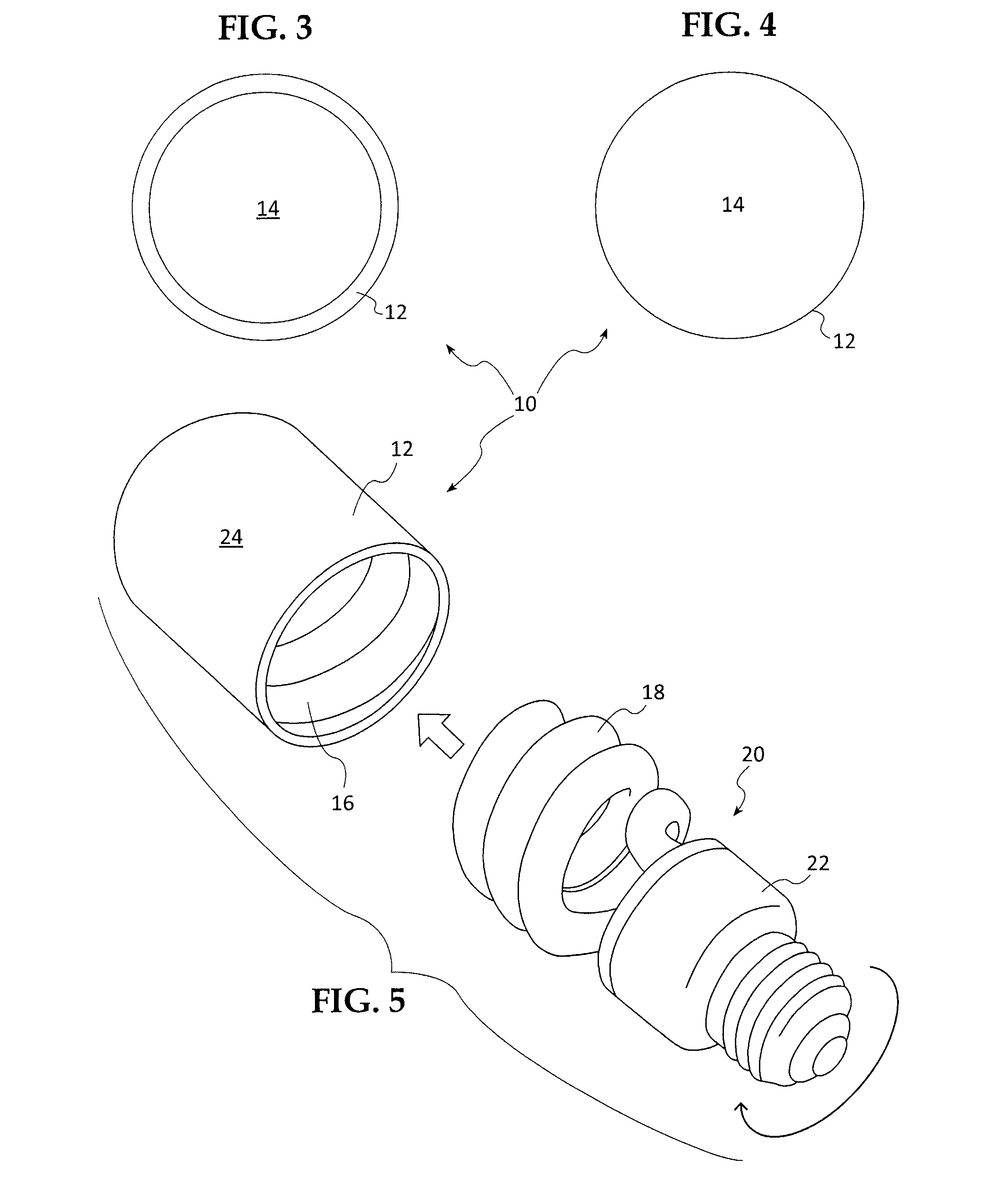
[0043]Referring to FIGS. 1-6, in a first embodiment, inventive cover 10 is a generally tubular sleeve 12 having an outer end 14 closed to form a cup or shell. The interior wall of the sleeve 12 is configured with broad shallow threads 16 as a negative of the CFL glass lighting tube elements, thereby being sized to permit the sleeve to be screwed-onto the spiral tube 18 of the CFL 20, covering to the ceramic, plastic or metal base 22 of the CFL. The exterior surface 24 is a smooth generally cylindrical shape, and the outer end 14 is closed and slightly domed. The intersection of the side wall with the dome end may be a crisp edge 26, or it may be a smooth chamfered curve.

[0044]FIG. 2B is the section view of the internal threads 16 of the shell 12; FIGS. 3 and 4 show the open and closed ends, respectively, while FIG. 5 shows how the bulb is screwed into the sleeve 12.

[0045]FIG. 1 also shows an optional 2-part construction, in which the cups are molded in snap-together halves along a p...

second embodiment

[0048]In a second embodiment shown in FIGS. 7 and 8, the cup 10 is deeper than the height of the CFL tube spiral 18 so that there is a head space 32 between the top of the bulb and the inside face of the cup end dome wall 14. This permits installing a metal or plastic threaded coupling tube or rod 34 into the axial center of the cup from the outside end, over which is inserted a radially extending plastic, fabric, metal or glass shade 36 by use of a finial nut 38 screwed onto the projecting coupling.

[0049]There are two variations of this embodiment: A) where the threaded coupling is formed integral with the exterior of the cup end as shown in FIG. 7; and B) where the cup end is bored and threaded to receive a standard or provided tubular threaded coupling as a retrofit assembly, shown in FIG. 8. In the FIG. 8 variation of this embodiment, the coupling 34 is threaded into a cup end center hole 40, a keeper nut 42 is threaded on the coupling inside the cup, a shade 36 having a center ...

third embodiment

[0051]In a third embodiment shown in FIG. 9, the inventive cover 10, here a cup, includes key-hole or other shaped slots 46, 48 formed in (48) or through (46) the side wall 12 of the cup 10, into which stand-off ribs 50 of shade 52 are inserted for supporting or suspending a shade from the cup exterior. Optionally, a double-ended key hole slot 54 may be used, so that the cup is universally useful to retain a shade for a CFL bulb mounted in a lamp 56, or ceiling fixture 44 (see FIG. 8).


PUM


Abstract

Screw-on or slip-on covers, in the form of transparent or translucent plastic sleeves for CFLs functioning as diffusers and cups for handling bulbs during installation, removal and as a safety receptacle for mercury-contaminated broken bulbs. The covers have interior surfaces contoured to the various sizes of CFL tube configurations, spiral or axially folded tubes, so that they are securely retained when screwed or slipped onto the tubes. The inventive covers may be used in any orientation, open end up, down or horizontal, so that they are equally useful for upright CFLs in lamps, horizontally oriented CFLs screwed into wall sockets, or downwardly oriented or angled CFLs screwed into horizontal or sloped ceiling fixtures. The inventive covers function as light diffusers and hide the tubes in more pleasing external shapes. Attractive sleeve colors, designs and surface textures are disclosed. Shades and shade frames may be secured to the inventive CFL covers.

Description

CROSS-REFERENCE TO RELATED APPLICATION[0001]This is the Regular US application corresponding to a U.S. Provisional Application Ser. No. 61 / 298,847, entitled Folded and Spiral-Tube Type Fluorescent Bulb Diffusion Cover and Shade Assemblies filed by the same inventor on Jan. 27, 2010, the priority of which is claimed under 35 US Code Sections 119, 120, ff.FIELD[0002]The application is directed to screw-on or slip-on covers, in the form of transparent or translucent plastic sleeves or cups, for folded-tube and spiral-tube type fluorescent bulbs, including CFL bulbs, which function as diffusion covers while hiding the tubes in more pleasing shapes, and at the same time serving as safety cups to assist in handling the bulbs during installation and removal, while serving as a safety receptacle for broken bulbs. A wide range of attractive sleeve colors, designs and surface textures are disclosed. Shades and shade frames may be secured to the inventive sleeves. The sleeve color can be selec...

Claims


Application Information

Patent Timeline
Patent Type & Authority Patents(United States)
IPC IPC(8): H01J1/02
CPCF21V3/02F21V17/04F21V17/12
Inventor GRUBER, KARL L.
Owner DIVERSIFIED ELECTRONICS
Learn More