
Optical reader capable of changing the incident angle of dark field illumination

a technology of incident angle and optical reader, applied in the field of optical readers, can solve the problems of increased illumination light source number, increased space, and increased manufacturing cost of devices of greater size and manufacturing costs

Inactive Publication Date: 2012-08-14
KOWA CO LTD
View PDF7 Cites 2 Cited by
  • Summary
  • Abstract
  • Description
  • Claims
  • Application Information

AI Technical Summary

Benefits of technology

The present invention provides an optical reader with a dark field illumination light source that can change the incident angle of dark field illumination in various ways to improve the visibility of captured images and image processing efficiency. The optical reader has an imaging device and a photographing optical system for reading images of an object, and includes a dark field illumination light source for illuminating the object at an angle of illumination that deviates from the optical axis of the photographing optical system. The reflection means is disposed in an illumination optical system that is disposed near the photographing optical system and includes an illumination light source different from the dark field illumination light source. The illumination optical system can be a bright field illumination optical system or a low-angle dark field illumination optical system. The invention allows for adjusting the angle of the dark field illumination light source to provide either a first angle of illumination for directly illuminating the object or a second angle of illumination for illuminating the object by reflection via the reflection means. The invention also allows for adjusting the reflection angle of the reflection means to select dark field illumination angles within a more diverse range of angles. The technical effects of the invention include improved visibility of captured images and image processing efficiency.

Problems solved by technology

The general usability of a device will be expanded if the types of incident angles of dark field illumination are increased, but a resulting problem is that the number of illumination light sources is increased, and more space is needed for the light sources, thereby leading to devices of greater size and greater manufacturing costs.
Furthermore, when the configuration of the dark field illumination is made variable, it is sometimes necessary to change the position of the illumination light source and change the direction of the illumination light source.
Unless suitably constructed, the range within which the illumination light source can be moved will be limited, or the size of the device and the costs might possibly be needlessly increased.

Method used


Image

  • Optical reader capable of changing the incident angle of dark field illumination
  • Optical reader capable of changing the incident angle of dark field illumination
  • Optical reader capable of changing the incident angle of dark field illumination

Examples


Embodiment Construction

[0024]The present invention will now be described in detail based on the illustrated embodiments. The embodiments are described with reference to an optical reader capable of reading semiconductor wafer markings or defects.

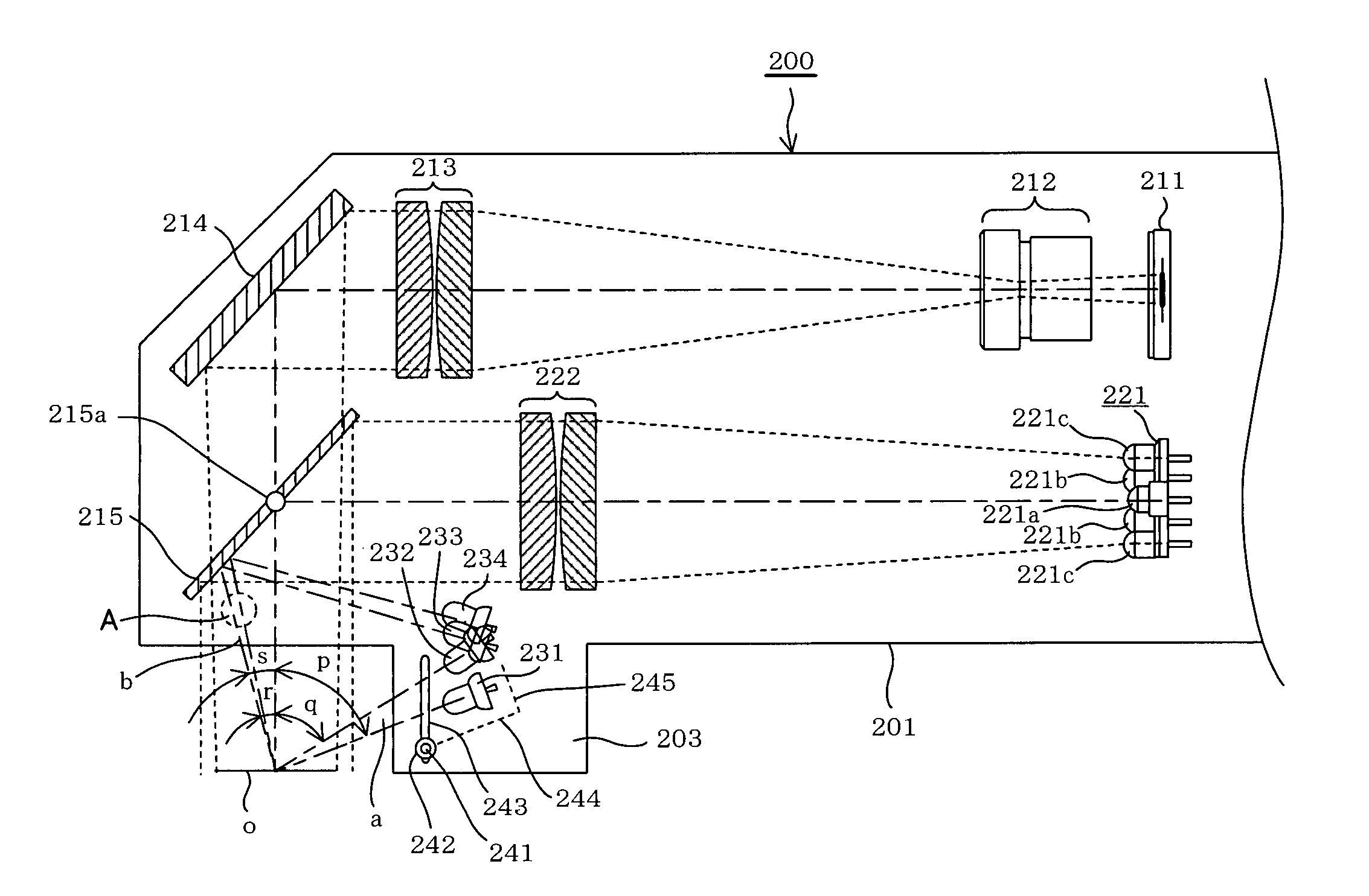
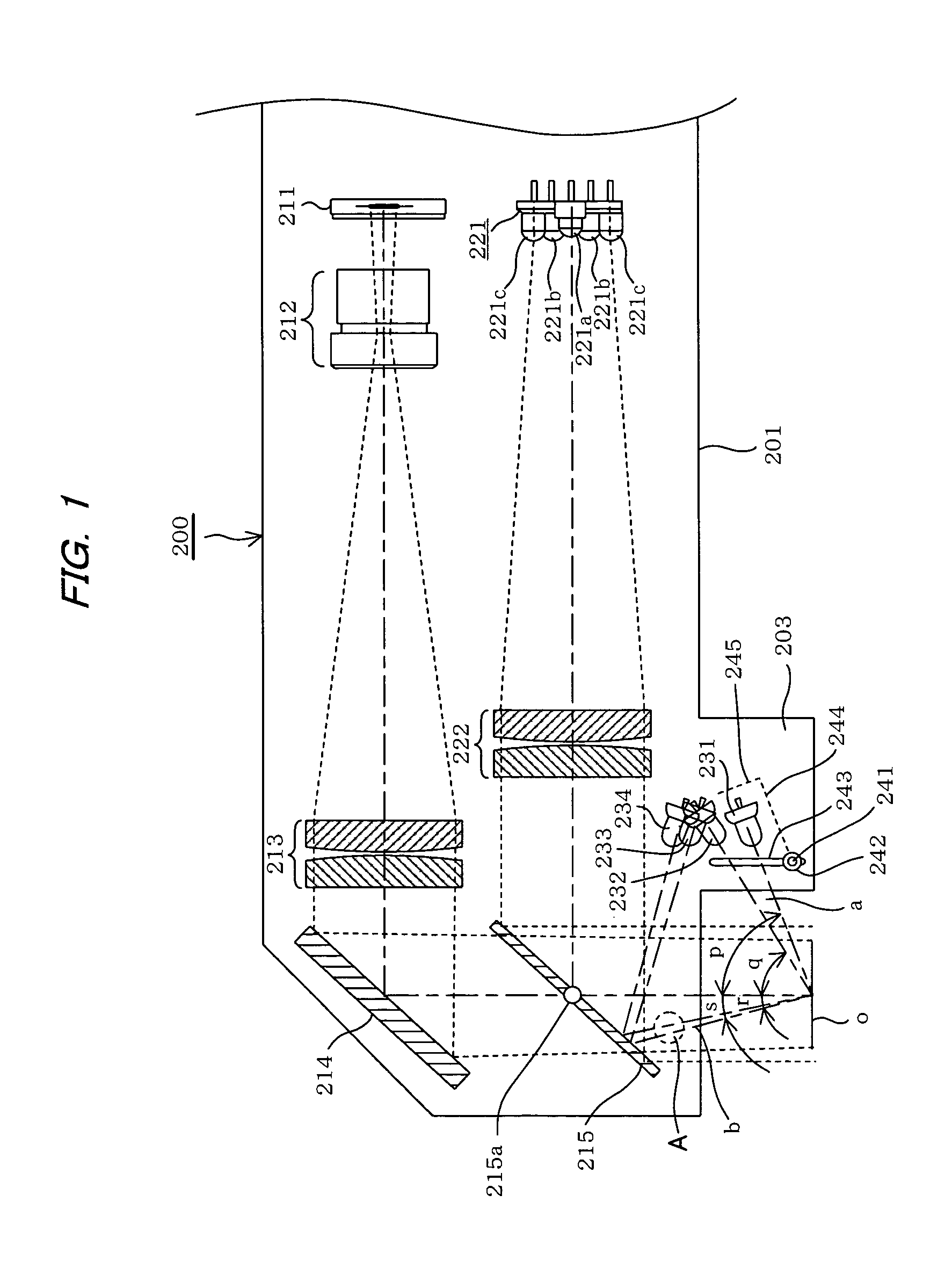
[0025]FIG. 1 shows the main structure of the photographing optical system and illumination optical system of an optical reader 200 according to the present invention. In FIG. 1, reference numeral 201 indicates the frame of the optical reader 200. The photographing optical system and illumination optical system are housed in the interior of the frame 201, which is composed of a plastic or metallic material, and is substantially L-shaped.

[0026]The photographing optical system includes an imaging device 211 that is composed of a CCD or CMOS sensor or the like, in front of which is disposed an optical system composed of a front lens assembly 213 and a rear lens assembly 212. A total reflection mirror 214 is disposed in front of the front lens assembly 213 to verticall...


PUM


Abstract

An optical reader includes an imaging device and an photographing optical system for reading images of an object such as a semiconductor wafer. An LED light source is provided as a dark field illumination light source for illuminating the object at an angle of illumination that deviates from the optical axis of the photographing optical system. The LED light source is supported by a swing-type support member having both ends secured to a housing of the optical reader using screws and nuts. This allows the angle and position of the dark field illumination light source to be adjusted so as to provide a first angle of illumination for illuminating the object directly with the illuminating light from the dark field illumination light source, or a second angle of illumination for illuminating the object by reflection from a half mirror that is disposed in an illumination optical system.

Description

BACKGROUND OF THE INVENTION[0001]1. Field of the Invention[0002]The present invention relates to an optical reader, and in particular to an optical reader having an imaging device and a photographing optical system for reading images of an object.[0003]2. Description of the Prior Art[0004]Images that are obtained with optical microscopes or semiconductor inspection devices vary greatly depending on how the object is illuminated (differences in amount of light, wavelength, and angle of incidence). Differences in image are directly related to image scanning or inspection performance and reliability. Dark field illumination is an important illumination means for making minute objects easier to see or for improving processing efficiency in OCR or other applications.[0005]Dark field illumination light sources are intended to illuminate objects at an angle of illumination that doesn't coincide with the optical axis of the photographing optical system. An illumination optical system includ...

Claims


Application Information

Patent Timeline
Patent Type & Authority Patents(United States)
IPC IPC(8): H04N7/18G06K7/10G06V10/141
CPCG01N21/8806G06K9/2027G01N21/9501G01N2021/8822G06V10/141
Inventor MIZUTA, TAKAHISASAKIYAMA, HIDETOMO
Owner KOWA CO LTD
Learn More