Apparatus and method for preventing reverse power flow of over current relay

a technology of reverse power flow and relay, applied in electromagnetic relays, dc-ac conversion without reversal, electric apparatus, etc., can solve problems such as failure to recover, delay in fault recovery time, and inability to additionally detect voltag

Inactive Publication Date: 2012-08-14
KOREA ELECTRIC POWER CORP
View PDF10 Cites 2 Cited by
  • Summary
  • Abstract
  • Description
  • Claims
  • Application Information

AI Technical Summary

Benefits of technology

[0013]The present invention is directed to an apparatus and method for preventing reverse power flow of an over current relay, which can allow a protection relay to normally operates, when a fault occurs at a load side of the protection relay and prevent the protection relay from malfunctioning when a fault occurs at a power source side of the protection relay.
[0014]The present invention is also directed to an apparatus and method for preventing reverse power flow of an over current relay, which can prevent a protection relay from malfunctioning due to reverse power flow when a fault occurs at a power source side of the protection relay.
[0020]The method for preventing reverse power flow may further include, after the comparing of the phase current with the neutral line current, determining that the reverse power flow occurs when the neutral line current is greater than the phase current ( ) and allowing the blocking relay to operate.

Problems solved by technology

This way of transformer connection makes the system analysis complicated and causes “false FI information” to be displayed on a screen of a distribution automation system when a distribution line fault occurs, which results in various problems such as a mistake in operation or a delay of fault recovery time.
However, a recloser or a circuit breaker installed in a distribution system which is in general use is a protection device which detects only the current through a current transformer and does not have an algorithm for detecting the reverse power flow, and a method of additionally detecting the voltage is technically impossible.
The substation circuit breaker, the recloser of the distribution line, and a client circuit breaker may malfunction due to the reverse power flow.
In particular, when a distribution system is interconnected with a distributed generation such as a solar photovoltaic power generation or a wind power generation, a Y-Δ connection is applied to an interconnecting transformer, and thus the reverse power flow severely occurs.
When a short circuit fault occurs, the directional over current relay operates normally, but when a ground fault occurs, it operates abnormally because a power flow direction changes with respect to the position of ground fault of each phase.
When a fault occurs at a power source side, a person in charge has to always stay in a substation due to the malfunction of the protection relay, or when a fault occurs at a load side in the distribution automation system, much time and manpower are required to find the fault position.
In particular, when a ground fault occurs in the same bank of the substation during distribution system operation, the substation circuit breaker disposed in a neighboring line, the recloser of the distribution line, the ground installed in a client circuit breaker and the current relay cannot detect the directivity by the reverse power flow and frequently malfunctions, whereby the power failure area increases.

Method used


Image

  • Apparatus and method for preventing reverse power flow of over current relay
  • Apparatus and method for preventing reverse power flow of over current relay
  • Apparatus and method for preventing reverse power flow of over current relay

Examples


Embodiment Construction

[0035]Hereinafter, exemplary embodiments of the present invention will be described in detail below with reference to the accompanying drawings such that those skilled in the art to which the present invention pertains can easily practice the present invention.

[0036]Like reference numerals designate like elements throughout the specification. In addition, when a unit or element is “electrically coupled” to another unit or element, it can be directly connected to another unit or element or be indirectly connected to another unit or element with one or more intervening units or elements interposed therebetween.

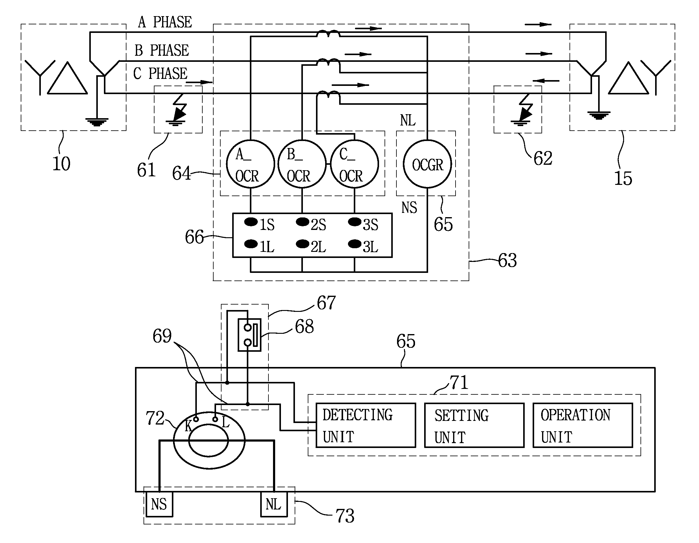
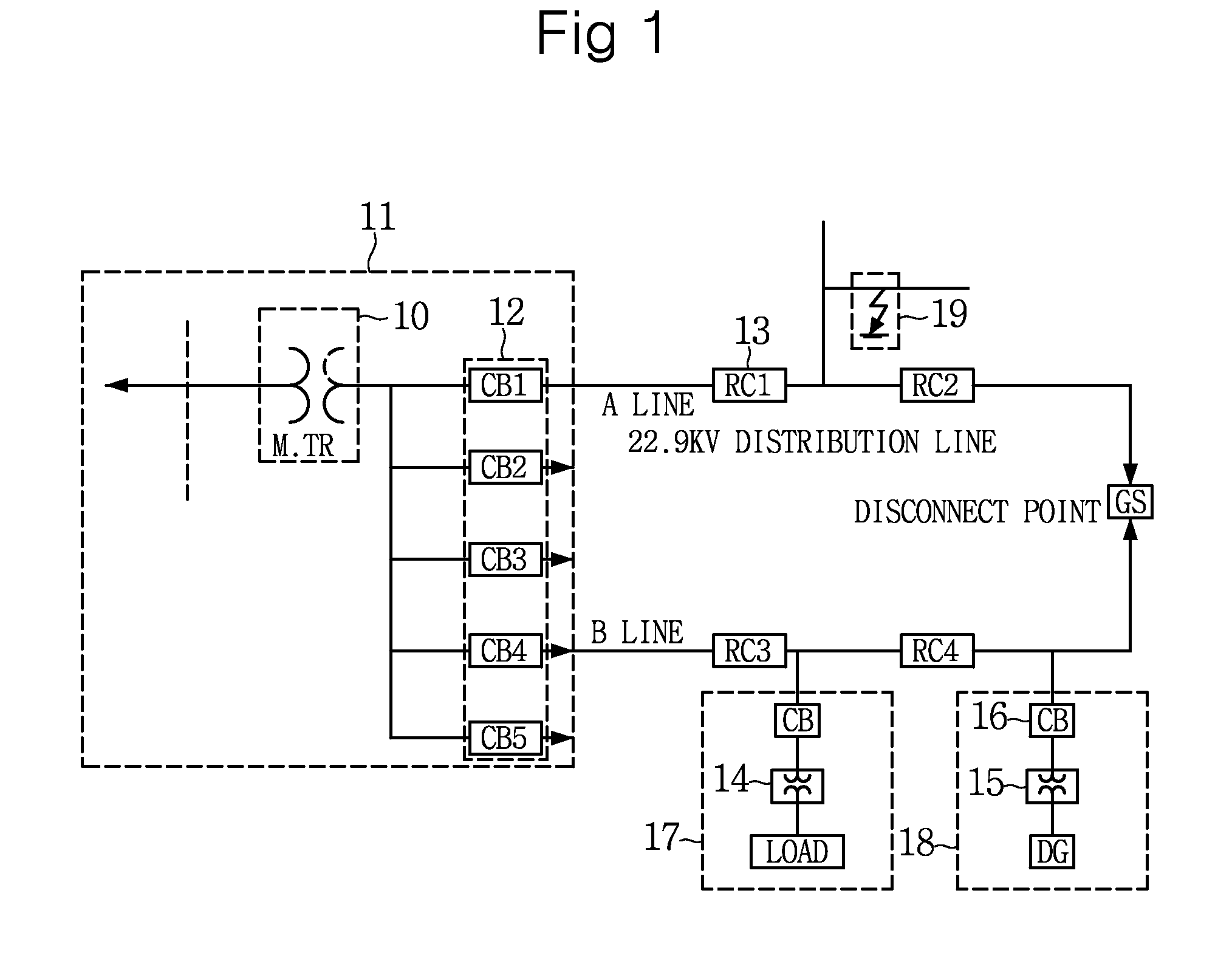
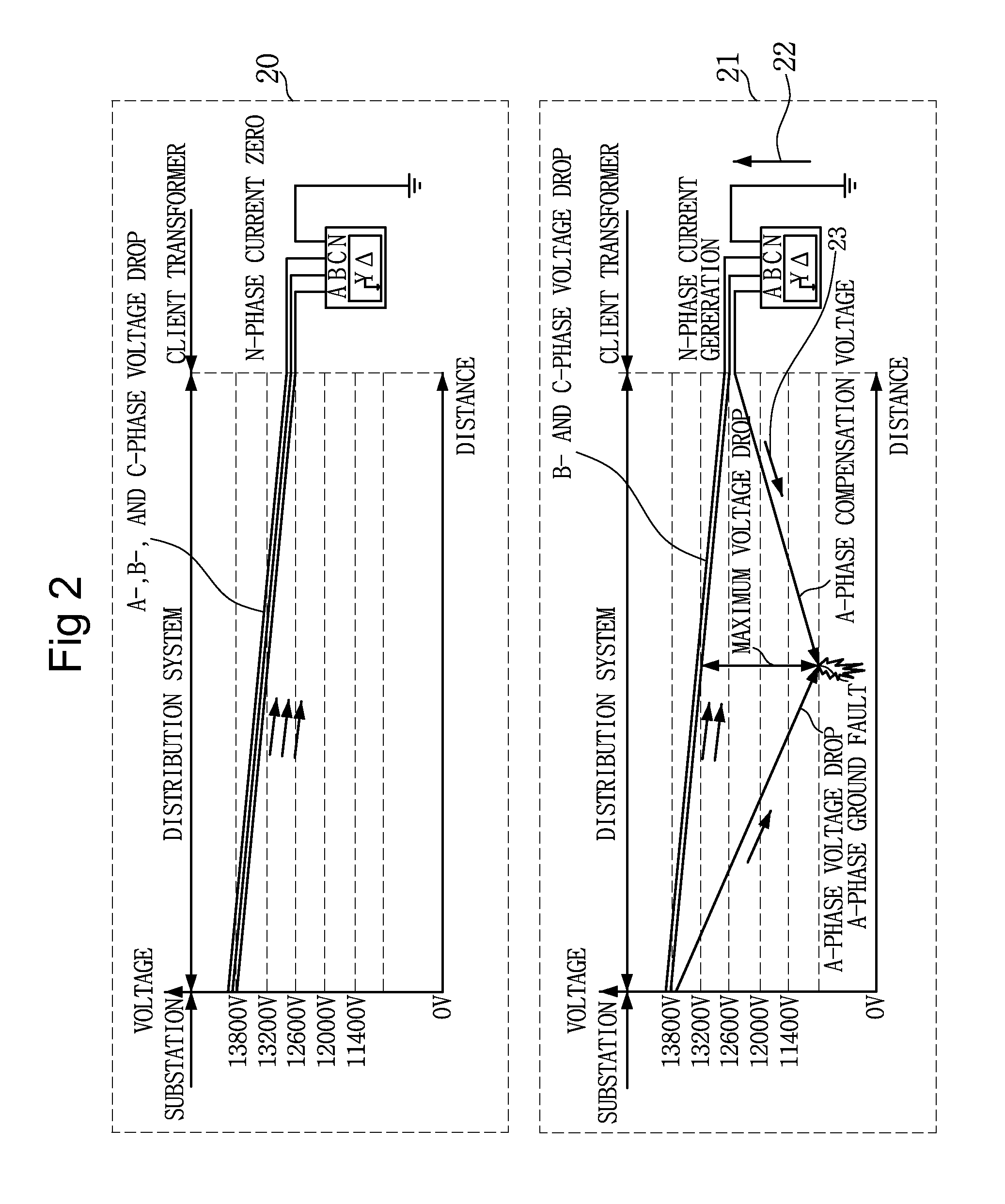
[0037]FIG. 1 is a single-line diagram for explaining a configuration of a general distribution system.

[0038]As illustrated in FIG. 1, a main transformer 10 of a 154 KV / 22.9 KV substation 11 has a Y-Δ-Y connection, a receiving client transformer 14 in a receiving client section 17 has a Δ-Y connection between a circuit breaker (CB) and a load, and a generating client transformer ...


PUM


Abstract

Provided is an apparatus and method for preventing reverse power flow of an over current relay. When a neutral line current is greater than a phase current, it is determined that a reverse power flow occurs, and thus a protection relay is prevented from malfunctioning. The apparatus for preventing reverse power flow of an over current relay includes: a detecting unit which detects a phase current and a neutral line current; a reverse power flow determining unit which is electrically connected to the detecting unit and compares the phase current and the neutral line current which are detected by the detecting unit to determine whether or not a reverse power flow occurs; a setting unit which is electrically connected to the reverse power flow determining unit and sets an operation time and the number of operation times of a protection relay; and an operation unit which is electrically connected to the setting unit and operates the protection relay in a manner set by the setting unit.

Description

CROSS-REFERENCE TO RELATED APPLICATION[0001]This application claims priority to and the benefit of Korean Patent Application No. 2008-0106159, filed on Oct. 28, 2008, the disclosure of which is incorporated herein by reference in its entirety.BACKGROUND[0002]1. Field of the Invention[0003]The present invention relates to an apparatus and method for preventing reverse power flow of an over current relay (OCR), and more particularly, to an apparatus and method for preventing reverse power flow of an over current relay, which can prevent a protection relay from malfunctioning due to reverse power flow in a distribution system.[0004]2. Discussion of Related Art[0005]Generally, when a line fault or load unbalance occurs in a line interconnected with a distributed generation, a substation circuit breaker, a recloser of a distribution line, an over current relay (OCR) or an over current ground relay (OCGR) of a client circuit breaker malfunctions due to reverse power flow caused by a conne...

Claims


Application Information

Patent Timeline
Patent Type & Authority Patents(United States)
IPC IPC(8): H02H3/00
CPCH02H3/081H02M7/42H01H51/00
Inventor SHIN, DONG-YEOL
Owner KOREA ELECTRIC POWER CORP
Why Eureka
Try Eureka