
Method for controlling mold clamping device

a mold and clamping device technology, applied in auxillary shaping apparatus, manufacturing tools, ceramic shaping apparatus, etc., can solve the problems of difficult to precisely control a position and a speed compared to electromotive-type injection molding machines, and achieve the effect of reducing variation in mold clamping positions, improving control precision, and lowering mold quality

Active Publication Date: 2012-08-14
NISSEI PLASTIC IND CO LTD
View PDF5 Cites 2 Cited by
  • Summary
  • Abstract
  • Description
  • Claims
  • Application Information

AI Technical Summary

Benefits of technology

The present invention provides a method for controlling a mold clamping device that can prevent molds from colliding with each other and improve molding quality and productivity while reducing costs. The method involves setting a speed control pattern for the mold clamping process and controlling the hydraulic pump to achieve the desired speed. This method also addresses the issue of variation in viscosity and volume of the hydraulic oil caused by temperature changes and the inertial force of the hydraulic actuator. By using a fixed speed control pattern and a current position detection system, the method ensures precise control of the mold clamping process and prevents damage to the molds.

Problems solved by technology

Generally, a hydraulic-type injection molding machine has an aspect that it is difficult to precisely control a position and a speed compared to an electromotive-type injection molding machine.
When supposing, as a hydraulic actuator, for example, a mold clamping cylinder equipped in a mold clamping device, even though feedback control is carried out for the positions, mold clamping positions (mold closing positions) or mold closing time periods largely vary among shots, causing a trouble such as breakage and damage from colliding a movable mold with a fixed mold.
This problem is more serious, when a mold closing speed is increased to shorten a mold closing time period (molding cycle time) in order to increase productivity.

Method used


Image

  • Method for controlling mold clamping device
  • Method for controlling mold clamping device
  • Method for controlling mold clamping device

Examples


Embodiment Construction

[0022]The invention will now be described in greater detail with preferred embodiments of the invention and drawings attached. However, it should be appreciated that the drawings attached are given not to specify the invention, but to facilitate understanding of the invention. In addition, detail description of a well-known part of the invention is omitted to avoid that the invention becomes unclear.

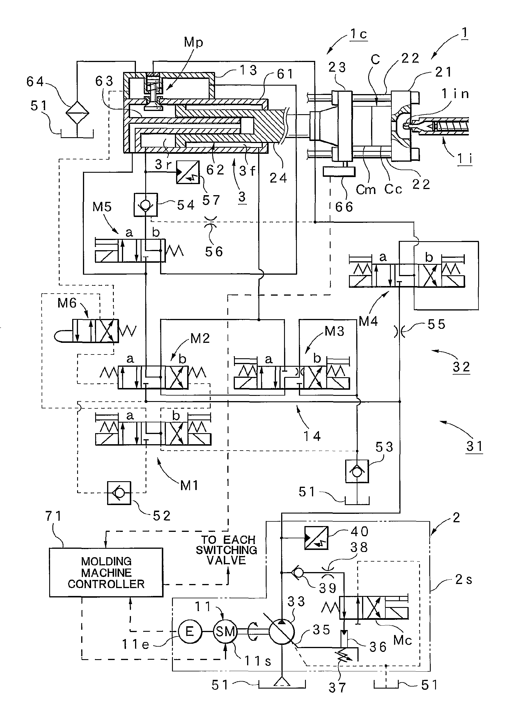
[0023]Firstly, a configuration of a mold clamping device 1c arranged in an injection molding machine 1, by which the control method according to this embodiment can be implemented, will be explained, with reference to FIG. 3.

[0024]In FIG. 3, 1 designates an injection molding machine, which is provided with an injection device 1i and a mold clamping device 1c. The mold clamping device 1c has a fixed platen 21 which is fixed in a molding machine bed (not shown), and a plurality of tie bars 22 . . . which dispose from this fixed platen 21 to a pressure receiving platen (not shown), and a mo...


PUM

PropertyMeasurementUnit
speedaaaaaaaaaa
closing speedaaaaaaaaaa
timeaaaaaaaaaa

Abstract

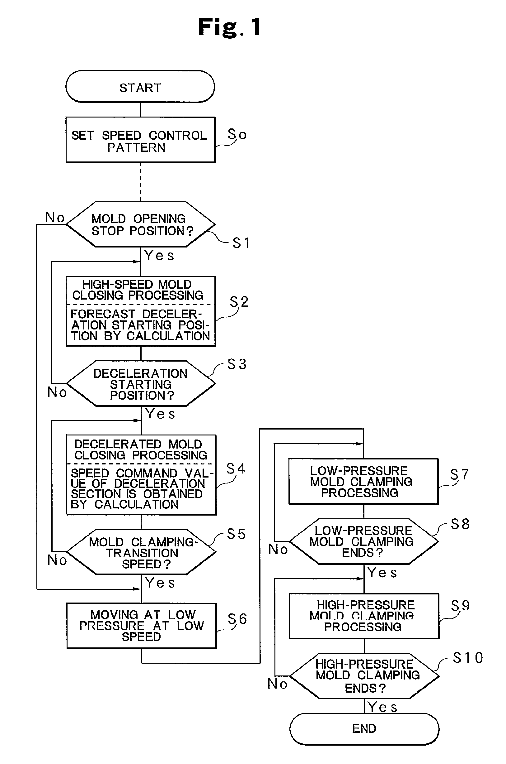
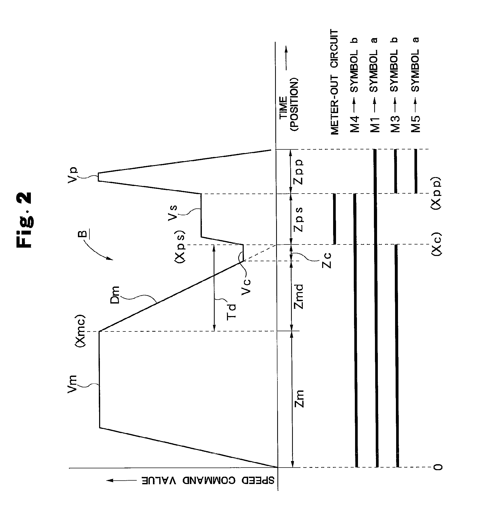
A predetermined speed control pattern B is sct. In a mold clamping process, in a mold closing section Zm, mold closing control is performed at a mold closing speed Vm, and based on a current mold closing speed Vd and a current mold closing position Xd, which are both detected, a deceleration starting position Xmc of the deceleration section Zmd, where the current mold closing speed Vd becomes a zero (O) at a virtual stop position Xc, is sequentially forecasted at each predetermined time interval by calculation. Upon reaching the deceleration starting position Xmc the deceleration section Zmd is started, and in the deceleration section Zmd, based on the detected current mold closing position Xd, a speed command value Dm corresponding to the speed control pattern B is obtained sequentially by calculation, and according to the speed command value Dm deceleration control is performed. Upon reaching a mold clamping-transition speed Vc, a predetermined mold clamping processing is performed via a low-pressure low-speed section Zc.

Description

TECHNICAL FIELD[0001]This invention relates to a method for controlling a mold clamping device which performs mold clamping control by driving a mold clamping cylinder by a hydraulic pump.BACKGROUND ART[0002]Generally, a hydraulic-type injection molding machine has an aspect that it is difficult to precisely control a position and a speed compared to an electromotive-type injection molding machine. In other words, in the case of the hydraulic type, as it uses hydraulic oil and a hydraulic actuator, viscosity, volume, and the like of the hydraulic oil changes according to temperature, and an inertial force is generated in the hydraulic actuator. These physical behaviors directly affect the control precision and responsiveness. In the case where, as a hydraulic pump, a variable discharge type hydraulic pump capable of controlling a discharge flow rate by varying the number of revolutions of a drive motor is used, length of the hydraulic circuit from the hydraulic pump to the hydraulic...

Claims


Application Information

Patent Timeline
Patent Type & Authority Patents(United States)
IPC IPC(8): B29C45/03
CPCB29C45/76B29C45/82B29C2945/76083B29C2945/7611B29C2945/76227B29C2945/76387B29C2945/76575B29C2945/76595B29C2945/76705B29C2945/76866
Inventor HAKODA, TAKASHIKOMAMURA, ISAMUOKADA, HARUONAKAMURA, KIYOSHI
Owner NISSEI PLASTIC IND CO LTD
Learn More