Dual band threat warning system

a threat warning and dual band technology, applied in the field of detection of incoming threats, can solve the problems of limiting the scope and speed of responses or actions of a system, and the difficulty of identifying, evading or mitigating incoming rockets or similar high-speed guided or un-guided munitions, etc., to reduce the false alarm rate, improve the detection of threats, and more accurate and effective countermeasures

Inactive Publication Date: 2012-08-21
LOCKHEED MARTIN CORP
View PDF9 Cites 6 Cited by
  • Summary
  • Abstract
  • Description
  • Claims
  • Application Information

AI Technical Summary

Benefits of technology

[0011]One embodiment of the present invention may be designed specifically for ground vehicle defense against RPGs (rocket propelled grenades). Such an embodiment of the invention may not require exquisite accuracy in azimuth and elevation but may require an accuracy of plus or minus three feet in the range measurement by the radar in order to trigger any appropriate countermeasures accurately. Appropriate countermeasures may include non-lethal shot projectors that throw shot in a wide pattern to intercept and destroy or detonate an incoming RPG. An embodiment of the present invention may also determine an expected impact location relative to the vehicle carrying the inventive system for more accurate and effective countermeasures deployment.
[0012]A sensor system according to the present invention configured for the above inventive embodiment may include an optical sensor system surrounded by a radar sensor system, with both systems potentially sharing a common set of electronic components. In one such embodiment, both systems may have a 360 by 60 degree field of view. Alternate embodiments of the present invention may have different fields of view depending on their specific application or configuration needs. One potential alternative embodiment may be an optical system with a 360 by 120 field of view and two separate range-finding systems, each with a non-overlapping 360 by 60 degree field of view. In yet further alternative embodiments, the field of view and configuration of the initial detection and ranging portions may be reversed or otherwise configured based on the operating and deployment requirements of the system. In embodiments where the detection and ranging systems operate on different technologies (i.e. millimeter-wave and sonar), it may be advantageous to use fewer shared components. In embodiments where the system is expected to be subject to damage from environmental or other factors, it may be advantageous to include redundant or otherwise fault-tolerant components in either or both sensors and / or in the electronics,
[0013]By combining detection and ranging sensors into a single system, embodiments of the present invention provide a number of advantages. In the radar and optical embodiment, both optical and radar systems produce false alarms. By requiring both an optical signature and radar signature together to identify a threat, the present invention reduces the false alarm rate to near zero. Radar only systems must transmit continuously to detect threats. The radar signal can be detected and the vehicle attacked. In addition, the constant radar emissions can create radiation hazards to nearby humans if they are exposed for a significant period of time. This embodiment of the inventive device is passive until a potential threat is optically identified. Only then is the radar activated and then only for the period of time needed to detect the threat.
[0014]The use of multiple, distinct detection bands in the present invention improves the detection of threats. All band signatures are required to confirm an attack. This feature is what reduces the false alarm rate. Further, by having at least one of the bands configured for passive detection and at least one band for active detection and only engaging the active detection system in response to a target acquired by the passive detection system, the present invention realizes the benefits of an active detection system while preventing others from easily or readily identifying the source of the active detection system. Embodiments of the present invention therefore provide accurate detection of potential threats or targets with a low false alarm rate.
[0015]Embodiments of the present invention also allow for a sensor system that realizes the benefits of an active detection paradigm while mitigating some of the downsides of that paradigm (specifically, reducing chances of detection and location of the active system by engaging active detection only for short periods and only after detection of a target or threat by the passive system).

Problems solved by technology

This limits the scope and speed of responses or actions possible for a system because of several issues, including the approach speed of a threat.
Such difficulties are especially pronounced with respect to identifying and evading or mitigating incoming rockets or similar high-speed guided or un-guided munitions.

Method used


Image

  • Dual band threat warning system
  • Dual band threat warning system
  • Dual band threat warning system

Examples


Embodiment Construction

[0024]The following detailed description of the invention refers to the accompanying drawings. The same reference numbers in different drawings identify the same or similar elements. Also, the following detailed description does not limit the invention. Instead, the scope of the invention is defined by the appended claims and equivalents thereof.

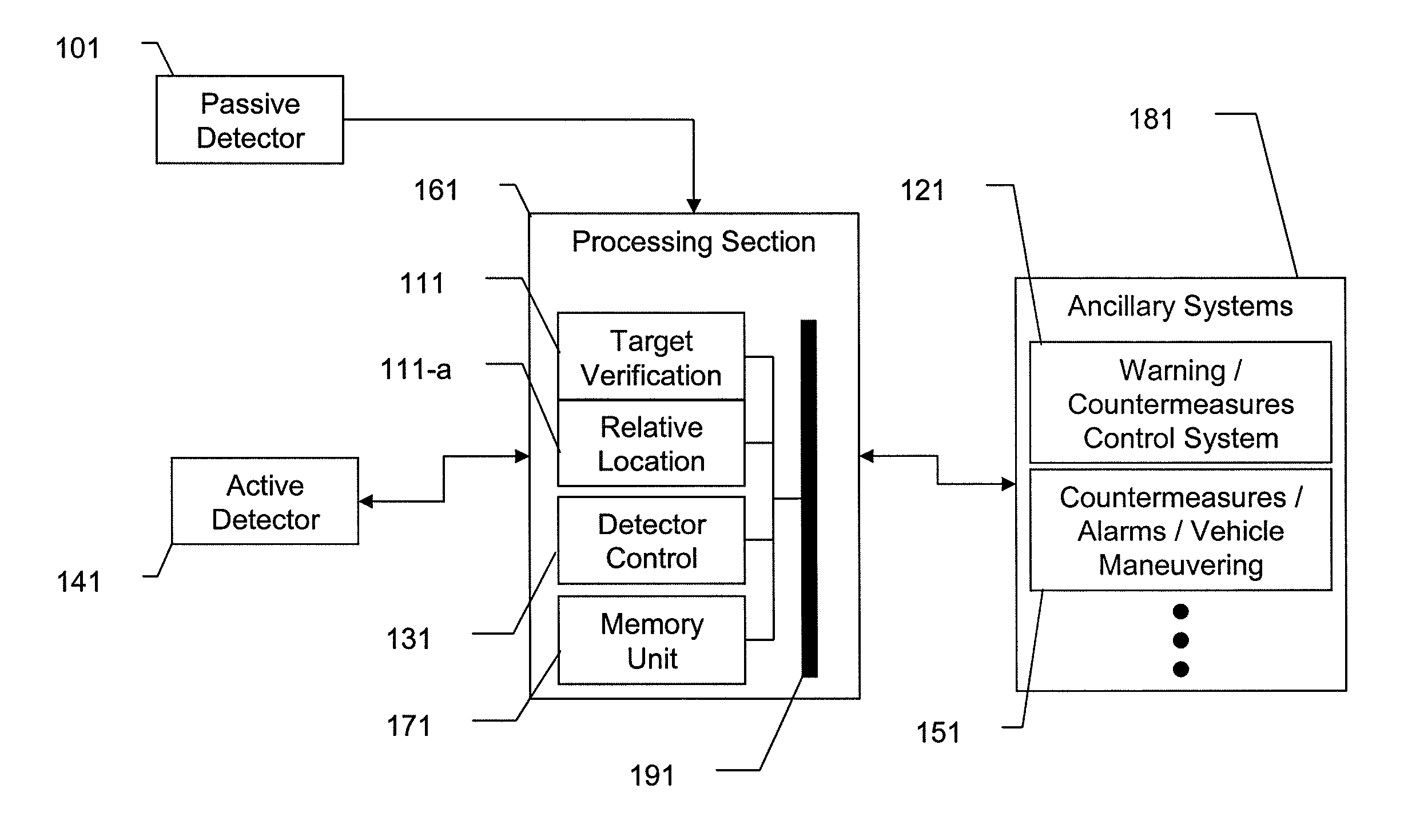
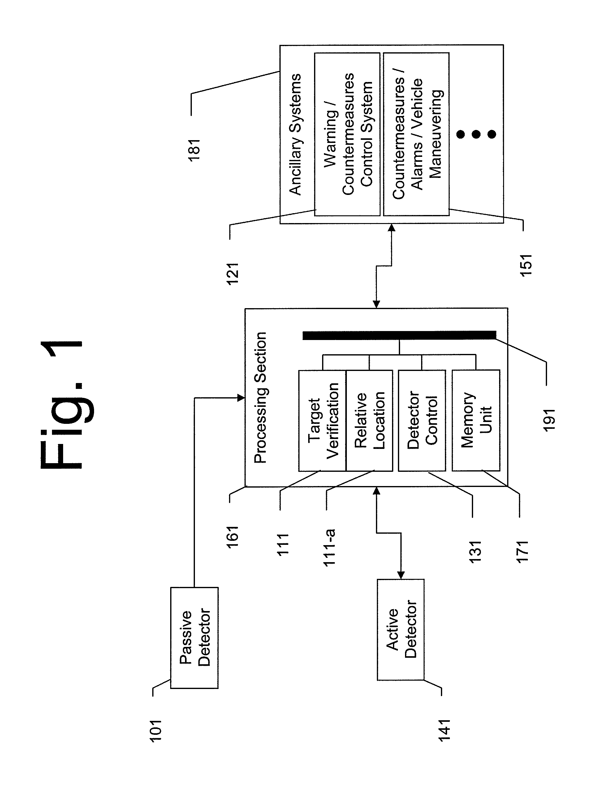
[0025]An embodiment of the present invention may include components depicted in FIG. 1. A passive optical detector 101 may be continually operating or may be manually activated when the system is engaged and prepared for operation. This may be a passive optical detector operable in visible, millimeter wave, infra-red or ultra-violet depending on the particular operating environment and threat or threat types being detected. Embodiments for land vehicles operating in urban areas may be equipped with a visible spectrum or an infra-red passive detector to detect launches of munitions such as rocket-propelled grenades (RPGs). Embodiments for sea...


PUM


Abstract

A system and method for dual-band detection of incoming threats using an initial passive detection system and a selectively activated active detection system. Advantages include improved threat detection accuracy, reduction of false alarms, and reduced radiation emission from the active system, thereby making the active system more difficult to detect and reducing irradiation levels of users and bystanders. Variations include systems employing passive optical or electro-optical detectors, systems employing active RADAR or LADAR detectors, and systems connected to alarm signal / threat mitigation systems. The system may be configured for use on ground vehicles or small watercraft. Variations of the system may be specifically configured to detect incoming munitions launches.

Description

CROSS REFERENCE TO RELATED APPLICATIONS[0001]This nonprovisional application claims the benefit of U.S. Provisional Application No. 61 / 107,882 filed on Oct. 23, 2008. The entire contents of the above application is hereby incorporated by reference.BACKGROUND OF THE INVENTION[0002]1. Field of the Invention[0003]The present invention relates generally to the detection of incoming threats and, more particularly, to methods and devices for both passively and actively detecting and tracking incoming threats such as rockets or missiles.[0004]2. Description of Related Art[0005]Military vehicles, both ground and air, require defensive systems to warn or automatically defend against attacks by rockets or missiles. These defensive systems require sensors that detect an incoming threat and determine whether the threat is real or not. If the threat is real, a defensive system may initiate countermeasures to defeat the threat or issue warnings to the crew to evade the threat.[0006]Previous defen...

Claims


Application Information

Patent Timeline
Patent Type & Authority Patents(United States)
IPC IPC(8): G06F19/00G06G7/80
CPCF41G5/08F41H11/02G01S3/784G01S13/867G01S17/023G01S13/862G01S13/865G01S17/86
Inventor WARREN, MICHAEL C.
Owner LOCKHEED MARTIN CORP
Why Eureka
Try Eureka