Methodology and tooling arrangements for increasing interlaminar shear strength in a ceramic matrix composite structure

a composite structure and ceramic matrix technology, applied in the direction of wind motors with parallel air flow, wind motors with perpendicular air flow, liquid fuel engine components, etc., can solve the problem of lack of sufficient shear strength to carry interlaminar shear loads

Inactive Publication Date: 2012-08-21
SIEMENS ENERGY INC
View PDF16 Cites 26 Cited by
  • Summary
  • Abstract
  • Description
  • Claims
  • Application Information

AI Technical Summary

Problems solved by technology

Conventional CMC components formed from two-dimensional fiber arrangements have sufficient in-plane strength, but may lack sufficient shear strength to carry interlaminar shear loads.

Method used


Image

  • Methodology and tooling arrangements for increasing interlaminar shear strength in a ceramic matrix composite structure
  • Methodology and tooling arrangements for increasing interlaminar shear strength in a ceramic matrix composite structure
  • Methodology and tooling arrangements for increasing interlaminar shear strength in a ceramic matrix composite structure

Examples


Embodiment Construction

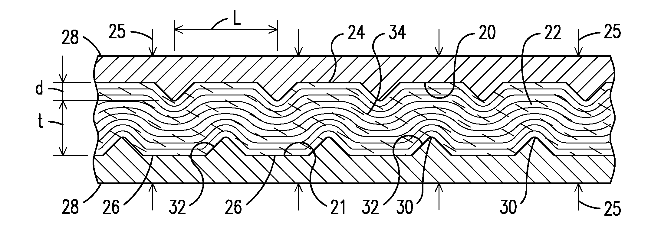
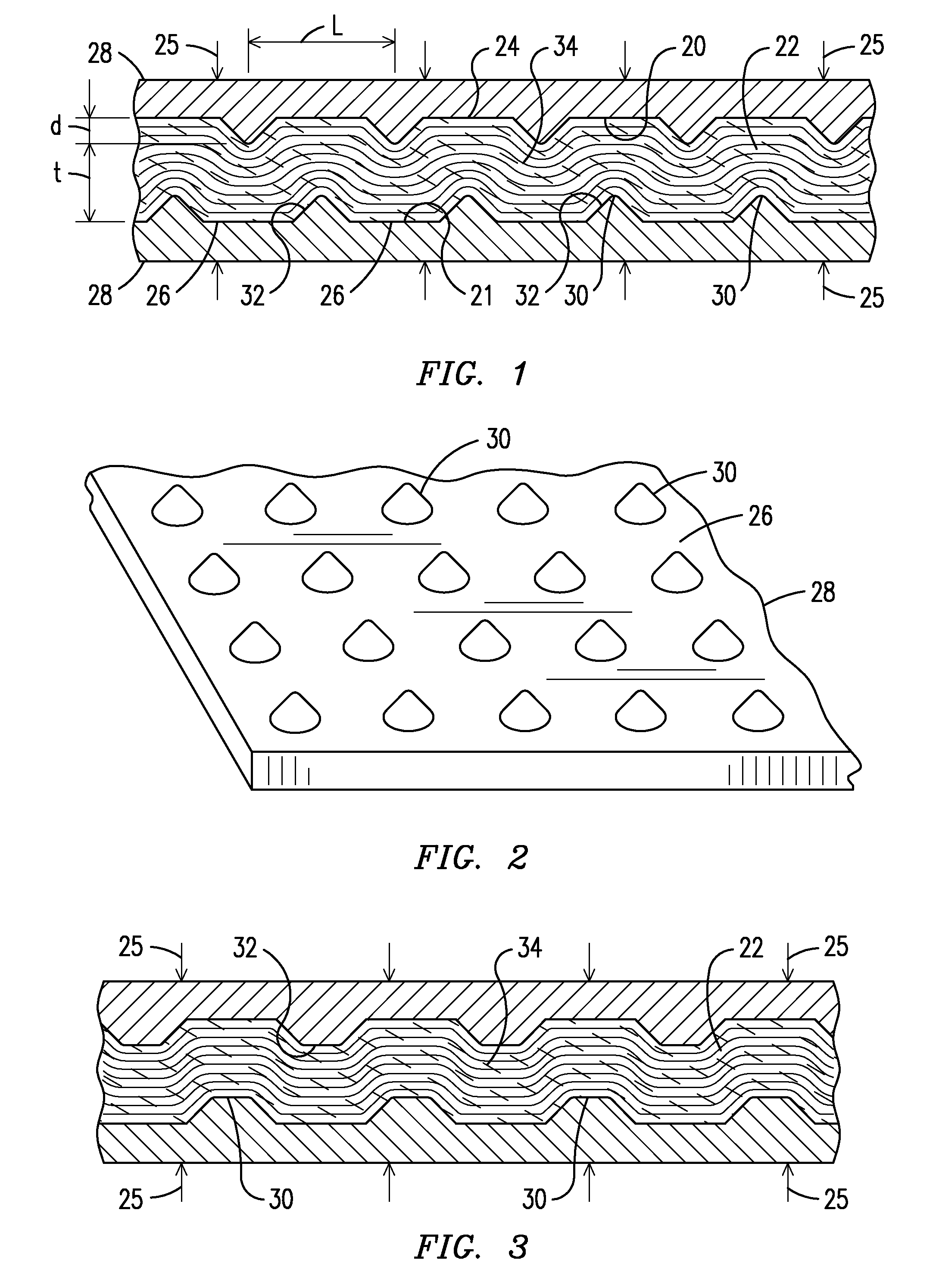
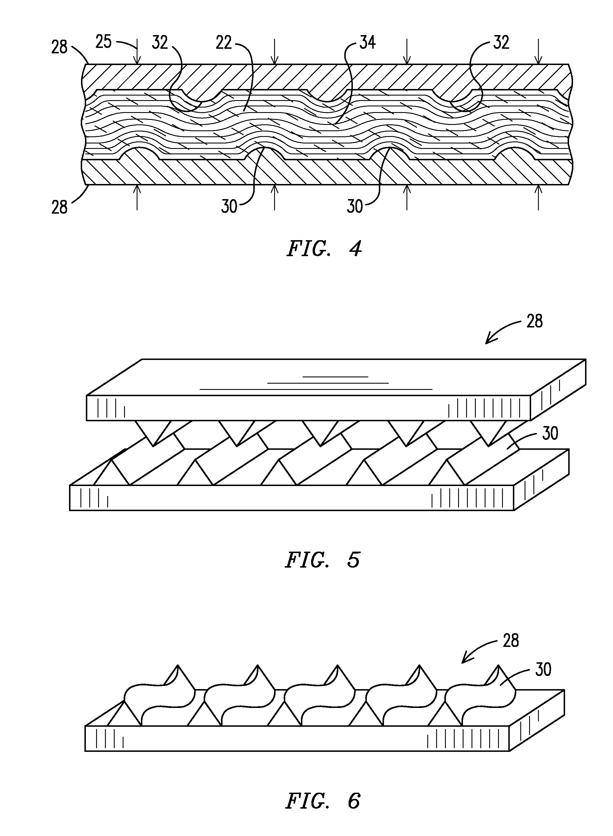
[0008]In accordance with one or more embodiments of the present invention, structural arrangements for fabricating a ceramic matrix composite (CMC) structure are described herein. In the following detailed description, various specific details are set forth in order to provide a thorough understanding of such embodiments. However, those skilled in the art will understand that embodiments of the present invention may be practiced without these specific details, that the present invention is not limited to the depicted embodiments, and that the present invention may be practiced in a variety of alternative embodiments. In other instances, methods, procedures, and components, which would be well-understood by one skilled in the art have not been described in detail to avoid unnecessary and burdensome explanation.

[0009]Furthermore, various operations may be described as multiple discrete steps performed in a manner that is helpful for understanding embodiments of the present invention. ...


PUM

PropertyMeasurementUnit
depthaaaaaaaaaa
depthaaaaaaaaaa
distanceaaaaaaaaaa

Abstract

Methodology and tooling arrangements for increasing interlaminar shear strength in a ceramic matrix composite (CMC) structure are provided. The CMC structure may be formed by a plurality of layers of ceramic fibers disposed between a top surface and a bottom surface of the composite structure. A plurality of surface recesses are formed on the surfaces of the structure. For example, each of the surfaces of the composite structure may be urged against corresponding top and bottom surfaces of a tool having a plurality of asperities. The plurality of surface recesses causes an out-of-plane sub-surface fiber displacement along an entire thickness of the structure, and the sub-surface fiber displacement is arranged to increase an interlaminar shear strength of the structure.

Description

FIELD OF THE INVENTION[0001]The present invention is generally related to ceramic matrix composite (CMC) structures for use in a high temperature combustion environment, and, more particularly, to tooling arrangements and / or techniques for increasing interlaminar shear strength of the CMC structure.BACKGROUND OF THE INVENTION[0002]Components made from CMC materials permit higher operating temperatures than do metal alloy materials due to the properties of ceramic materials. One example of a high temperature operational environment occurs in state of the art turbine engine applications. The high temperature capability results in reduced cooling requirements, which results in higher power, greater efficiency, and / or reduced emissions from the engine. Conventional CMC components formed from two-dimensional fiber arrangements have sufficient in-plane strength, but may lack sufficient shear strength to carry interlaminar shear loads.BRIEF DESCRIPTION OF THE DRAWINGS[0003]The invention is...

Claims


Application Information

Patent Timeline
Patent Type & Authority Patents(United States)
IPC IPC(8): B32B3/00B32B5/12F04D29/00F03B3/00
CPCB32B18/00C04B35/80C04B2235/945C04B2237/38C04B2237/64Y10T156/1039Y10T428/24479Y10T428/24529Y10T156/1044Y10T428/24132Y10T428/24124Y10T428/249928
Inventor MORRISON, JAY A.MERRILL, GARY B.
Owner SIEMENS ENERGY INC
Why Eureka
Try Eureka