
Method and apparatus to sharply focus aerosol particles at high flow rate and over a wide range of sizes

a technology of aerosol particles and sharp focus, which is applied in the direction of isotope separation, particle separator tubes, and associated parts, to achieve the effects of high flow rate, high concentration factor (c), and high r

Inactive Publication Date: 2012-08-21
SOC EURO DE ANALISIS DIFERENCIAL DE MOVILIDAD
View PDF2 Cites 2 Cited by
  • Summary
  • Abstract
  • Description
  • Claims
  • Application Information

AI Technical Summary

Benefits of technology

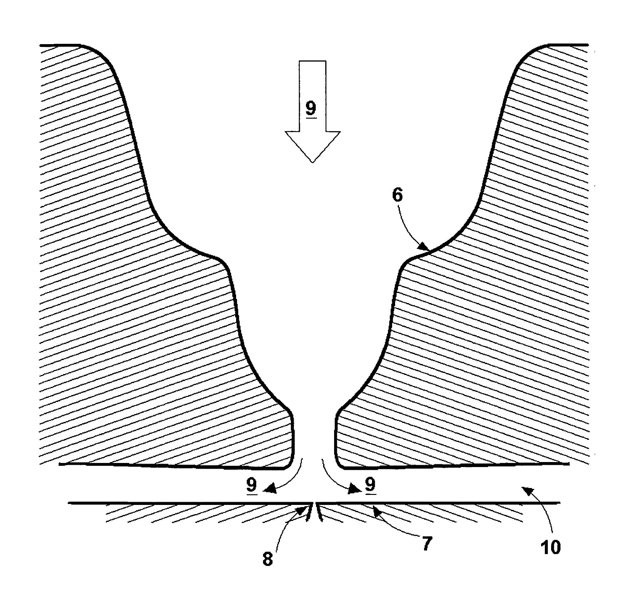
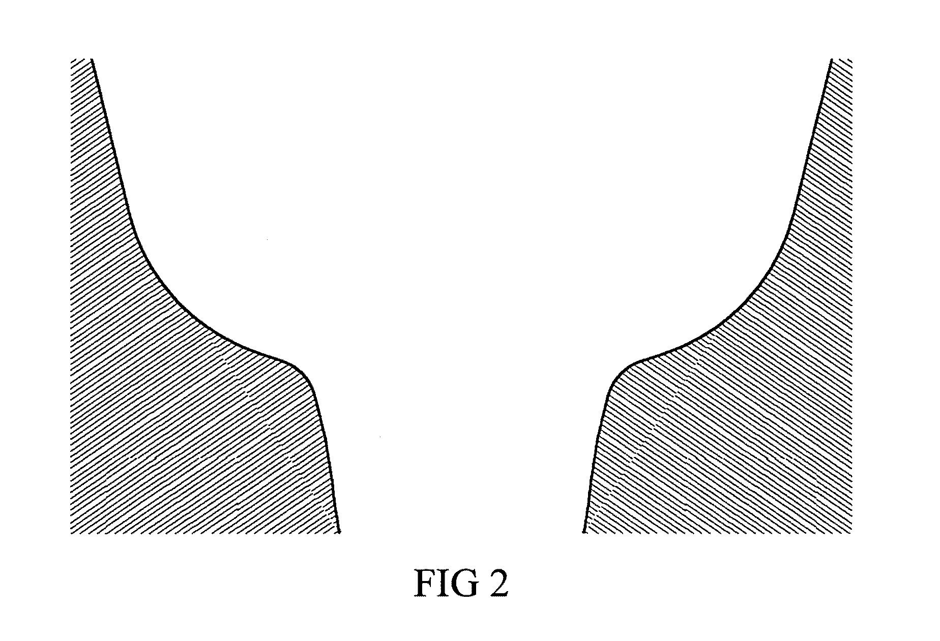
"The invention is a focusing device that can concentrate a wide range of particle sizes at high flow rates. The device uses a single convergence geometry that avoids flow detachment, but requires a ladder of contractions to focus sharply on particles of different sizes. The new device avoids the need for multiple focusing nozzles and uses a smoothly designed aerodynamic configuration to prevent instabilities. The device also has a unique geometry that allows for effective focusing of both small and large particles."

Problems solved by technology

But the turbulent transition problem characteristic of all prior focusing lenses (at all but relatively small values of Re) requires the development of a new aerodynamic configuration avoiding entirely flow detachment.

Method used


Image

  • Method and apparatus to sharply focus aerosol particles at high flow rate and over a wide range of sizes
  • Method and apparatus to sharply focus aerosol particles at high flow rate and over a wide range of sizes
  • Method and apparatus to sharply focus aerosol particles at high flow rate and over a wide range of sizes

Examples


Embodiment Construction

[0080]The composite focusing nozzle already described can be used in a variety of ways according to the present invention. It can be used without further additions to concentrate narrowly into a focal region the particles suspended in a large sampled flow rate of gas. These particles can then be interrogated optically, for instance to determine if they contain dangerous pathogens (Kasparian et al. 2007[31]; Davitt et al. 2006[34]). Alternatively, the focused particle beam can be impacted on a surface for various purposes. For instance, to write a narrow line, to alter this surface as a result of the spatially concentrated high-speed impact of relatively hard particles, to cut the surface, etc. Higher particle velocities may be achieved without degrading the focus by extending longitudinally the final nearly cylindrical region of the last nozzle section, as in a gun, keeping it slightly conical to provide acceleration to maintain the laminar flow. While a comparable result may be ach...


PUM

PropertyMeasurementUnit
Reynolds numbersaaaaaaaaaa
sizesaaaaaaaaaa
flow rateaaaaaaaaaa

Abstract

A method and an apparatus are described to focus sharply a wide range of particle sizes for particles suspended in a relatively high flow rate of carrier gas. The particles are accelerated through a continuously converging ladder of smooth contractions, each designed such that: (i) the flow remains laminar at substantial Reynolds numbers; (ii) a certain band of particle sizes is focused in each contraction, without substantial defocusing of larger particle focused in one or several preceding contractions; (iii) the form, length, and ratio of entry to exit diameter of each contraction, as well as the number of consecutive contractions are chosen such that all particles within a given relatively wide range of sizes are focused at the end of the ladder of contraction steps into a relatively narrow focal region. The focusing apparatus coupled to a collector device constitutes a new type of virtual impactor, termed a focusing virtual impactor, which can also be used as a powerful particle concentrator.

Description

CROSS REFERENCE TO RELATED APPLICATION[0001]This application claims the benefit of priority to U.S. Provisional Patent Application No. US61 / 131,878, filed on Jun. 13, 2008.U.S. PATENT DOCUMENTS CITED[0002]U.S. patent application Ser. No. 12 / 012,771, by J. Fernandez de la Mora, with priority date of 5 Feb. 2007[0003]U.S. Pat. No. 4,383,171; Sinha; M. P., Giffin; C. E., Norris; D. D., Friedlander; S. K, Particle analyzing method and apparatus, May 10, 1983[0004]U.S. Pat. No. 5,270,542; P. H McMurry; D. B. Kittleson; P. J. Ziemman; P. Liu, Apparatus and method for shaping and detecting a particle beam; Dec. 14, 1993.[0005]U.S. Pat. No. 6,040,574, Jayne; John T., Worsnop; Douglas R., Kolb; Charles E., Atmospheric-particle analyzer, Mar. 21, 2000OTHER PUBLICATIONS CITED[0006][1] Robinson, A. On the Motion of Small Particles in a Potential Field Flow, Communications in Pure and Applied Mathematics, IX, 69-84 (1956).[0007][2] Chen B. T., Yeh H. C., Cheng Y. S., Performance of a modified vi...

Claims


Application Information

Patent Timeline
Patent Type & Authority Patents(United States)
IPC IPC(8): H01J49/04
CPCG01N1/2208G01N1/4022G01N1/4077G01N15/0266G01N1/2211G01N15/0255G01N2001/2223G01N2001/4027
Inventor VIDAL-DE-MIGUEL, GUILLERMOFERNANDEZ-DE-LA-MORA, JUAN
Owner SOC EURO DE ANALISIS DIFERENCIAL DE MOVILIDAD
Learn More