
Dielectric ceramic and laminated ceramic capacitor

a technology of dielectric ceramic and laminated ceramic, which is applied in the direction of fixed capacitors, inorganic chemistry, electrical apparatus, etc., can solve the problems of reducing the resistance to dielectric ceramic reduction, reducing the configuration difficulty of capacitors, and not always suitable for constituting dielectric ceramic layers. , to achieve the effect of improving the dielectric constant, increasing the dielectric constant, and reducing the calcination temperatur

Active Publication Date: 2012-08-21
MURATA MFG CO LTD
View PDF12 Cites 0 Cited by
  • Summary
  • Abstract
  • Description
  • Claims
  • Application Information

AI Technical Summary

Benefits of technology

[0017]In the dielectric ceramic according to the invention, preferably, a predetermined mount of Ba is further substituted for Sr at the A site of the SrTiO3 main component. Such substitution of Ba can further improve the dielectric constant.
[0018]In the dielectric ceramic according to the invention, the addition of a predetermined amount of M (M is at least one of Mn and V) or the addition of a predetermined amount of Si allows the calcination temperature to be decreased.
[0019]In the dielectric ceramic according to the invention, the addition of a predetermined amount of Ca can improve the temperature characteristics of the capacitance.
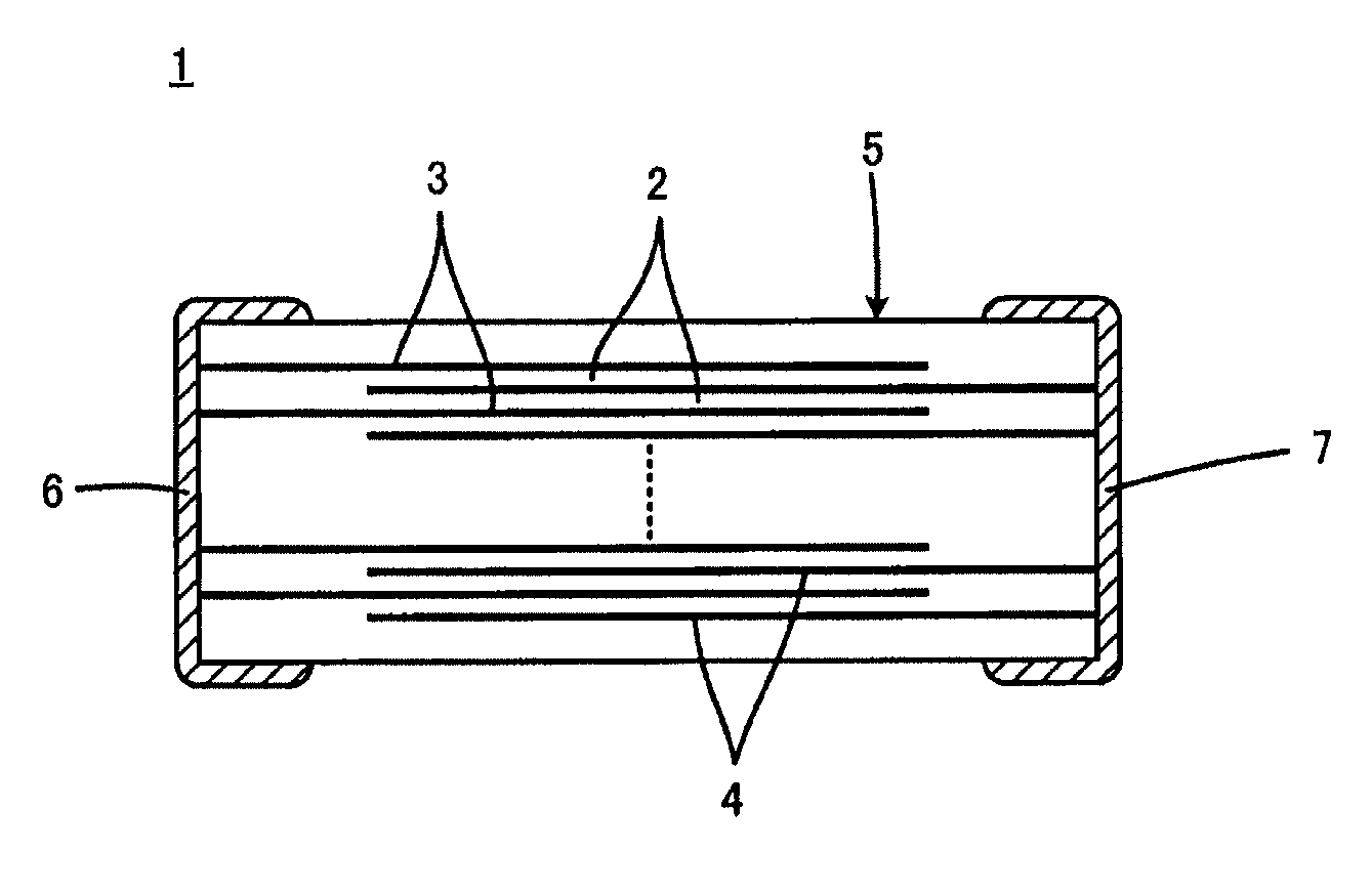
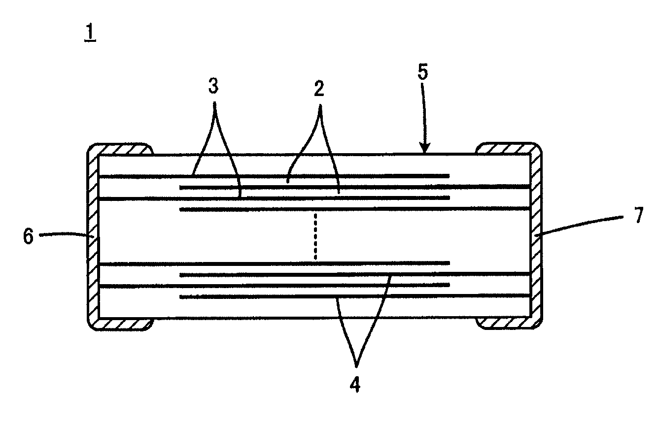
[0020]Thus, when the dielectric ceramic according to the invention is used to configure a laminated ceramic capacitor, the improvement in the dielectric constant of the dielectric ceramic layer allows the laminated ceramic capacitor to be reduced in size. Further, use of the dielectric ceramic to configure a laminated ceramic capacitor allows the dielectric ceramic layers and internal electrodes containing a base metal as its main component to be calcined simultaneously. Therefore, the cost of the laminated ceramic capacitor can be reduced, and the range of options can be expanded for the internal electrode material.

Problems solved by technology

However, SrTiO3 dielectric ceramics generally have low dielectric constants, and thus have the defect of difficulty in reduction of the size of capacitors configured with the use of such dielectric ceramics.
However, PbTiO3 and Bi2O3 decrease the resistance to reduction of dielectric ceramic material.
Therefore, PbTiO3 and Bi2O3 are not always suitable for constituting dielectric ceramic layers in laminated ceramic capacitors which have internal electrodes containing a base metal as their main components.
From this aspect, it is not easy to increase the dielectric constants of SrTiO3 dielectric ceramics.

Method used


Image

  • Dielectric ceramic and laminated ceramic capacitor
  • Dielectric ceramic and laminated ceramic capacitor

Examples


experimental example 1

[0038]First, respective powders of TiO2, SrCO3, and SnO2 were prepared as starting materials. These powders were blended to have a composition indicating each value of x and m in the composition formula: (Sr1-xSnx)mTiO3 shown in Table 1. Next, this blended powder was mixed and ground in a ball mill, and dried then to obtain a mixed powder.

[0039]Next, the mixed powder was thermally treated at a temperature of 1050° C. for 2 hours in an atmosphere composed of a N2—H2 mixed gas with an oxygen partial pressure of 10−10 MPa to obtain a powder containing (Sr1-xSnx)mTiO3 as its main component. This powder was subjected to dry grinding to give a ceramic raw material powder.

[0040]A polyvinyl butyral binder and an organic solvent containing ethanol were added to this raw material powder and mixed in a ball mill, thereby preparing a ceramic slurry.

[0041]Next, this ceramic slurry was subjected to sheet forming by the doctor blade method to obtain a ceramic green sheet with a thickness of 12 μm....

experimental example 2

[0055]The dielectric ceramic main component employed was the composition of the sample 6 with x=0.100 and m=1.00 in the composition formula: (Sr1-xSnx)mTiO3, manufactured in Experimental Example 1, to which a mol of MO (M is Mn or V) and b mol of SiO2 was added as shown in Table 2 with respect to 100 mol of the main component, and an evaluation was carried out in the same way as in Experimental Example 1. The results are shown in Table 2.

[0056]

TABLE 2SampleMCalcinationDielectricTanLog ρNumberxmspeciesabTemperatureConstantδ (%)(Ω· m)1010.1001.00Mn0.0000.013004500.808.31020.1001.00Mn0.0050.013004500.808.31030.1001.00Mn0.0100.012504300.809.01040.1001.00Mn0.2500.012504300.8010.51050.1001.00Mn0.5000.012504200.8011.01060.1001.00Mn1.0000.012254200.8011.01070.1001.00Mn2.5000.012004000.809.81080.1001.00Mn5.0000.012003800.806.51100.1001.00Mn0.0000.113004500.808.31110.1001.00Mn0.0000.212004600.808.31120.1001.00Mn0.0002.012004600.808.41130.1001.00Mn0.0005.011504000.807.71150.1001.00V0.0203.0120...

experimental example 3

[0060]For the dielectric ceramic main component, the composition of the sample 6 with x=0.100 and m=1.00 in the composition formula: (Sr1-xSnx)mTiO3, manufactured in Experimental Example 1, was used together with 0.500 mol of MnO, 2.0 mol of SiO2, and further c mol of CaO with respect to 100 mol of this main component as shown in Table 3, ΔC (−55) and ΔC (125) were evaluated as shown in Table 3.

[0061]ΔC (−55) refers to a rate of change (%) in capacitance at −55° C. with the capacitance at 25° C. as a reference, whereas ΔC (125) refers to a rate of change (%) in capacitance at 125° C. with the capacitance at 25° C. as a reference.

[0062]

TABLE 3ΔCSampleCalcinationΔC(125)NumberxmM speciesabcTemperature(−55) (%)(%)2010.1001.00Mn0.5002.00120070−352020.1001.00Mn0.5002.00.1120065−302030.1001.00Mn0.5002.010120030−282040.1001.00Mn0.5002.015120023−262050.1001.00Mn0.5002.025120012−18

[0063]Table 3 shows that for samples 202 to 205 with the added amount c of CaO from 0.1 mol to 25 mol with respec...


PUM

PropertyMeasurementUnit
dielectric constantaaaaaaaaaa
tan δaaaaaaaaaa

Abstract

A dielectric ceramic for use in dielectric ceramic layers has a main component represented by a composition formula of (Sr1-x-ySnxBay)TiO3, wherein x is 0.005≦x≦0.24, y is 0≦y≦0.25 in the composition formula. Preferably, the dielectric ceramic includes 0.01 mol to 5 mol of M (M is at least one of Mn and V) calculated as MO and / or 0.2 mol to 5 mol of Si calculated as SiO2, with respect to 100 mols of the main component, and more preferably, further includes 0.1 mol to 25 mol of Ca calculated as CaO with respect to 100 mols of the main component. The dielectric ceramic has an increased dielectric constant permitting size reduction when used in a laminated ceramic capacitor.

Description

BACKGROUND OF THE INVENTION[0001]1. Field of the Invention[0002]The present invention relates to a strontium titanate (SrTiO3) dielectric ceramic, and a laminated ceramic capacitor configured with the use of the dielectric ceramic.[0003]2. Description of the Related Art[0004]SrTiO3 dielectric ceramics are preferably used in capacitors for temperature compensation since the capacitances of capacitors configured with the use of these dielectric ceramics have good linearity for their temperature coefficients. Furthermore, SrTiO3 dielectric ceramics are also used in high-voltage capacitors.[0005]However, SrTiO3 dielectric ceramics generally have low dielectric constants, and thus have the defect of difficulty in reduction of the size of capacitors configured with the use of such dielectric ceramics.[0006]In order to eliminate the defect mentioned above, a dielectric ceramic as described in, for example, Japanese Patent Laid-Open No. 7-45122 (Patent Document 1) has been proposed. The die...

Claims


Application Information

Patent Timeline
Patent Type & Authority Patents(United States)
IPC IPC(8): H01G4/20H01G4/06C04B35/00
CPCB32B18/00C01G23/002C04B35/47C04B35/6268H01G4/1227H01G4/30C01P2002/52C01P2006/40C04B2235/3208C04B2235/3215C04B2235/3239C04B2235/3262C04B2235/3293C04B2235/3418C04B2235/6025C04B2235/656C04B2235/6582C04B2235/6584C04B2235/6588C04B2235/768C04B2237/346C01G23/003
Inventor SUZUKI, SHOICHIROTAKEDA, TOSHIKAZU
Owner MURATA MFG CO LTD
Learn More