Command reordering based on command priority

a command priority and command technology, applied in the direction of instruments, computing, electric digital data processing, etc., can solve the problems of time-wasting and ineffective memory access method, and the inability of memory controller to provide maximum dram bandwidth to a computer system, so as to reduce memory access latency and raise memory bandwidth

Inactive Publication Date: 2012-08-21
SUNPLUS TECH CO LTD
View PDF5 Cites 9 Cited by
  • Summary
  • Abstract
  • Description
  • Claims
  • Application Information

AI Technical Summary

Benefits of technology

[0008]The object of the present invention is to provide a control system for accessing synchronous DRAM memory, so as to reduce memory access latency and raise the memory bandwidth to near the maximal number of the DRAM component in a computer system.
[0009]Another object of the invention is to provide a control system mechanism for accessing synchronous DRAM memory, so as to generate a plurality of DRAM commands, which are belonged to different DRAM bank, and access the DRAM by interleaving mechanism to achieve maximization of the system performance.

Problems solved by technology

Since various system bus masters request the memory accesses that are for different data processing purpose or flow control of software program, it is difficult to find the same active page using in the previous memory access command and the following memory access command.
It is obvious that this method of memory access is time-wasting and ineffective.
In the case, the memory controller can't provide maximal DRAM bandwidth to a computer system.

Method used


Image

  • Command reordering based on command priority
  • Command reordering based on command priority
  • Command reordering based on command priority

Examples


Embodiment Construction

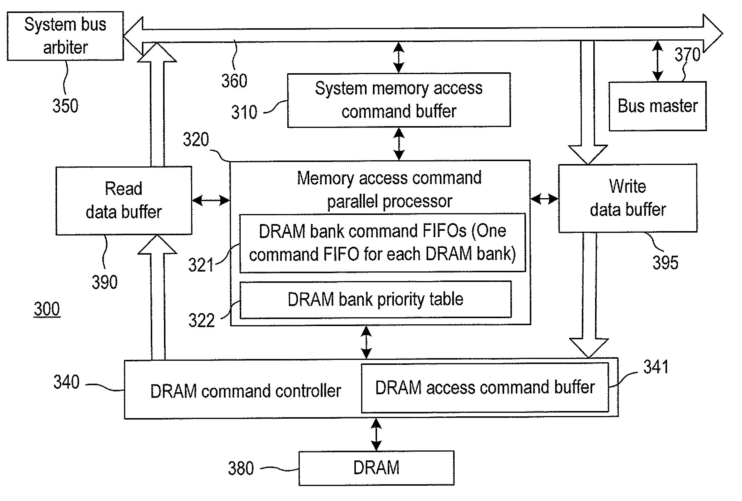
[0022]With reference to FIG. 3, there is shown a control system 300 for memory access in accordance with the invention, which includes a system memory access command buffer 310, a memory access command parallel processor 320, a DRAM command controller 340, a system bus arbiter 350, a read data buffer 390, and a write data buffer 395.

[0023]The system bus arbiter 350 receives memory access command request from a system bus master 370 through a system bus 360. The system memory access commands can be linear address mode of memory access commands or two-dimension address mode (start X-Address, Y-Address, X-Length and Y-Length) of memory access commands.

[0024]The system memory access command buffer 310 is connected to the system bus 360, in order to temporarily store multiple system memory access commands.

[0025]The memory access command parallel processor 320 is connected to the system memory access command buffer 310, in order to decode a system memory access command and then generate m...


PUM


Abstract

A control system for memory access includes a system memory access command buffer, a memory access command parallel processor, a DRAM command controller and a read data buffer. The system memory access command buffer stores plural system memory access commands. The memory access command parallel processor is connected to the system memory access command buffer for fetching and decoding the system memory access commands to plural DRAM access commands, storing the DRAM access commands in DRAM bank command FIFOs, and performing priority setting according to a DRAM bank priority table. The DRAM command controller is connected to the memory access command parallel processor and a DRAM for receiving the DRAM access commands, and sending control commands to the DRAM. The read data buffer is connected to the DRAM command controller and the system bus for storing the read data and rearranging a sequence of the read data.

Description

BACKGROUND OF THE INVENTION[0001]1. Field of the Invention[0002]The invention relates to the technical field of DRAM (Dynamic Random Access Memory) access and, more particularly, to a control system and method for synchronous DRAM access.[0003]2. Description of Related Art[0004]With the progress of semiconductor technology, the access speed of DRAM has improved gradually. In past twenty years, the access speed of DRAM has increased from several MHz to several GHz, and the number of latency cycles of non-active bank memory access has increased gradually. For example, the number of latency cycles of non-active bank memory access in SDR is 3 to 5, and the numbers of latency cycles of non-active bank memory access in DDR-II and DDR-III are 12 to 25.[0005]A computer system or an image processing system comprises various system bus masters. Each system bus master has a specific function, such as video decoding, video encoding, video display, audio signal decoding, audio signal play, DMA, ...

Claims


Application Information

Patent Timeline
Patent Type & Authority Patents(United States)
IPC IPC(8): G06F13/18
CPCG06F12/0607G06F13/1626
Inventor HUANG, MING CHUANLEE, CHIA HAOCHOU, HAN LIANG
Owner SUNPLUS TECH CO LTD
Why Eureka
Try Eureka