Tar-free gasification system and process

a gasification system and gasification process technology, applied in the field of gasification system and process, can solve problems such as tar formation, and achieve the effect of preventing tar formation and less construction and maintenance costs

Active Publication Date: 2012-08-28
LUMMUS TECH INC
View PDF13 Cites 2 Cited by
  • Summary
  • Abstract
  • Description
  • Claims
  • Application Information

AI Technical Summary

Benefits of technology

[0005]Historically, tar formation has been a major source of problem of heat exchange surface fouling and downstream filter plugging. The current inventive gasification process and system is significantly simpler, and less expensive to construct and maintain than previous systems, while simultaneously preventing the formation of tar.
[0006]Use of the system and process of the current invention maximizes the recovery of energy stored within the carbonaceous feedstock. The invention involves the partial combustion of recycled dry solids and the drying of carbonaceous slurry feedstock in two separate reactor zones of a two stage gasifier to thereby produce mixture products comprising synthesis gas. The syngas produced from the high temperature first stage reaction zone of the gasifier is then quenched in the second stage reaction zone into a low temperature syngas. A slurry feed stock is then introduced into the second stage to reduce the temperature of the final syngas exiting the second stage reaction zone of the gasifier. The temperature is reduced in order to be below that where tar formation occurs. This temperature is approximately 350-900° F., depending upon the type of feedstock utilized.
[0007]Certain embodiments of the present invention relate to a process for gasifying a carbonaceous material comprises the steps of a) introducing a dry feedstock into a reactor lower section and partially combusting therein with a gas stream comprising an oxygen-containing gas or steam thereby evolving heat and forming products comprising synthesis gas and molten slag; b) passing the synthesis gas from step a) upward into a reactor upper section, whereby the synthesis gas from step a) is cooled by one or more cooling agents; c) drying a slurry of particulate carbonaceous material in a liquid carrier with the cooled synthesis gas from step b) in the reactor upper section, thereby forming mixture products comprising a solid stream and a gaseous stream; d) passing the mixture products through a separating device whereby the solid stream is separated from the gaseous stream; and e) recycling the solid stream back to the reactor lower section. In such process, the hot synthesis gas produced in the reactor lower section is carried upward, thereby heating and / or vaporizing the cooling agent introduced in the second stage, such that the temperature of the mixture product formed in the second stage is reduced. Another aspect of the present invention relates to a system for gasifying a carbonaceous material comprising: a) a reactor lower section for partially combusting a dry feedstock with a gas stream comprising an oxygen-containing gas or steam to produce heat and products comprising synthesis gas and molten slag, wherein the reactor lower section comprises one or more dispersion devices for introducing the gas stream and the dry feedstock; b) a reactor upper section for cooling the synthesis gas from the reactor lower section followed by drying a slurry of particulate carbonaceous material in a liquid carrier with the cooled synthesis gas to produce mixture products comprising a solid stream and a gaseous stream; c) a separating device for separating the solid stream from the gaseous stream. In such system, the hot synthesis gas produced in the reactor lower section is carried upward, thereby heating and / or vaporizing the cooling agent introduced in the second stage, such that the temperature of the mixture product formed in the second stage is reduced.

Problems solved by technology

Historically, tar formation has been a major source of problem of heat exchange surface fouling and downstream filter plugging.

Method used


Image

  • Tar-free gasification system and process
  • Tar-free gasification system and process

Examples


Embodiment Construction

[0014]The following detailed description of various embodiments of the invention makes reference to the accompanying FIGURE and illustrates a specific embodiment in which the invention can be practiced. This embodiment is intended to describe aspects of the invention in sufficient detail to enable those skilled in the art to practice the invention. Other embodiments can be utilized and changes can be made without departing from the scope of the present invention. The following detailed description is, therefore, not to be taken in a limiting sense. The scope of the present invention is defined only by the appended claims, along with the full scope of equivalents to which such claims are entitled.

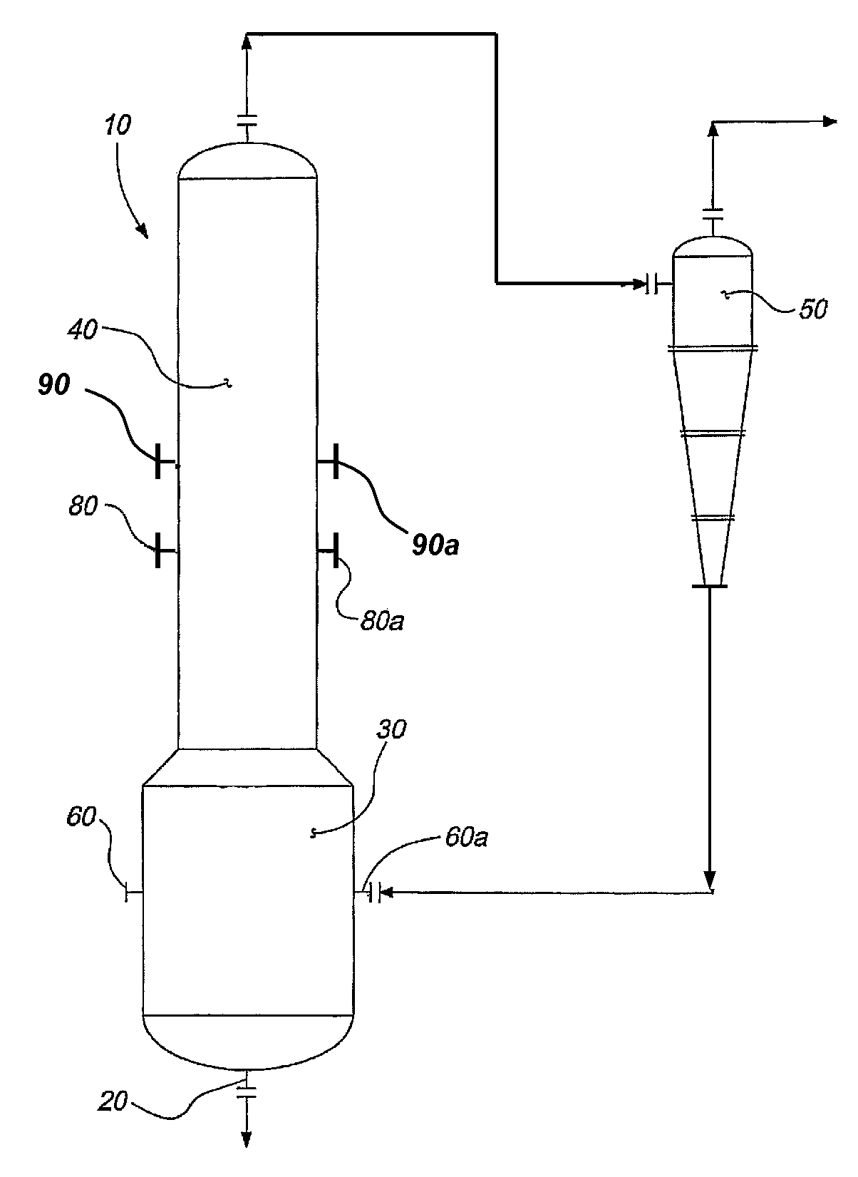
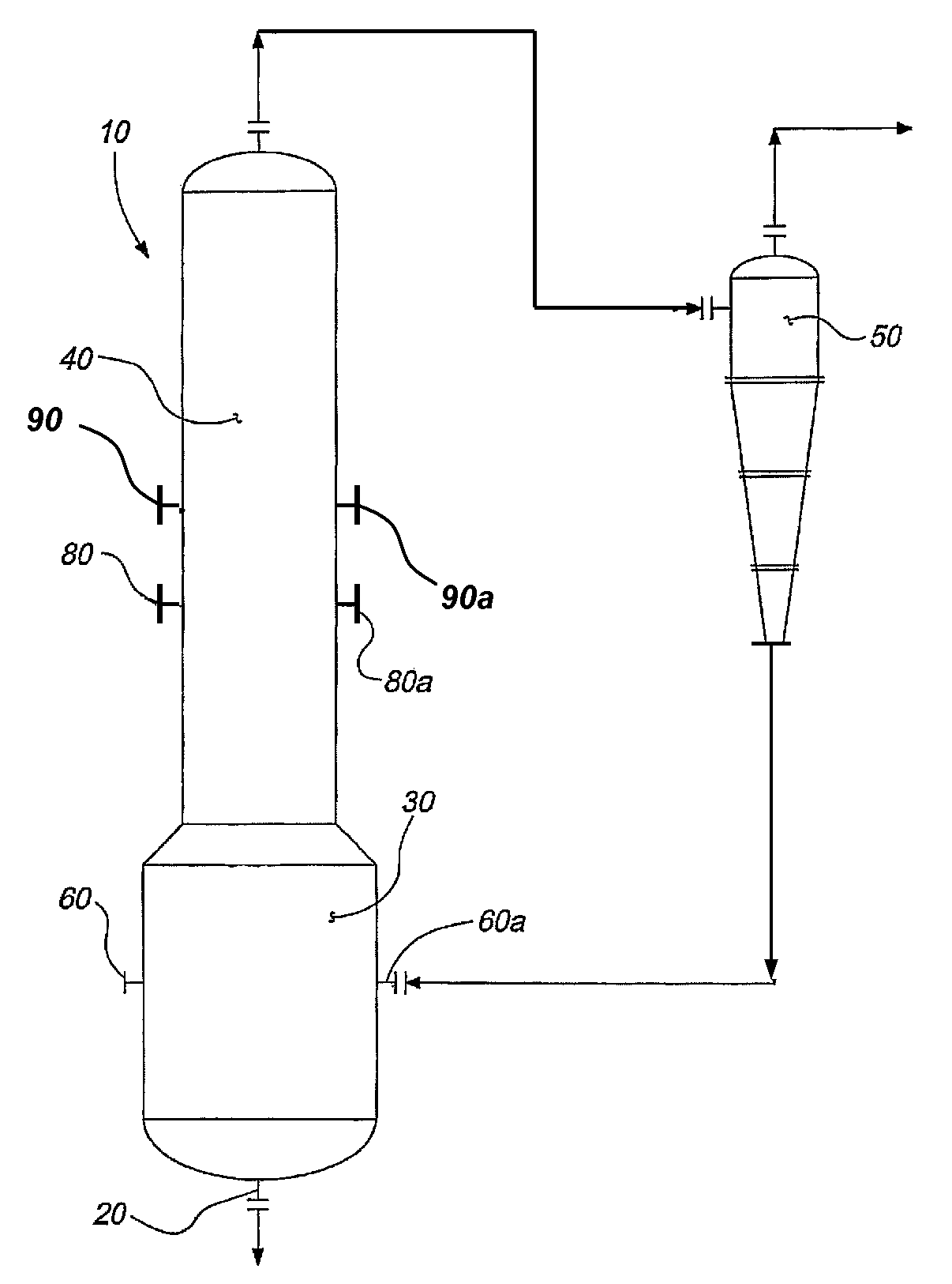
[0015]Referring to FIG. 1, one embodiment of the present invention provides a gasification reactor, indicated generally by reference numeral 10, that comprises a reactor lower section 30 and a reactor upper section 40. The reactor lower section 30 defines the first stage reaction zone of the...


PUM

PropertyMeasurementUnit
pressureaaaaaaaaaa
temperatureaaaaaaaaaa

Abstract

A novel tar-free gasification process and system is disclosed that involves the partial combustion of recycled dry solids and the drying of a slurry feedstock comprising carbonaceous material in two separate reactor zones in a two stage gasifier, thereby producing mixture products comprising synthesis gas. The synthesis gas produced from the high temperature first stage reaction zone is then quenched in the second stage reaction zone of the gasifier prior to introduction of a slurry feedstock. The temperature of the final syngas exiting the second stage reaction zone of the gasifier is thereby moderated to be in the range of about 350-900° F., which is below the temperature range at which tar is readily formed, depending upon the type of carbonaceous feedstock utilized.

Description

BACKGROUND OF THE INVENTION[0001]The present invention relates generally to a gasification system and process for converting generally solid feedstock such as carbonaceous material into desirable gaseous products such as synthesis gas. The gasification system and process must be designed to be simple, yet maximize carbon conversion efficiency.[0002]Three basic types of system and processes have been developed for the gasification of carbonaceous materials. They are: (1) fixed-bed gasification, (2) fluidized-bed gasification, and (3) suspension or entrainment gasification. The present invention relates to the third type of system and process-suspension or entrainment gasification. More particularly, the present invention relates to a two stage entrained gasification system and process for gasifying carbonaceous materials.[0003]The flexibility of the two stage gasifier design can be exploited by maximizing the slurry feed rate to the lower temperature second stage, thereby utilizing t...

Claims


Application Information

Patent Timeline
Patent Type & Authority Patents(United States)
IPC IPC(8): B01J8/00C01B3/00C07C1/02C10J3/16C10J3/46C10J3/54C01B3/02C07C1/00
CPCC10J3/56C10J3/485C10J3/721C10J3/74C10J3/78C10J3/845C10J3/84C10J2300/093C10J2300/0943C10J2300/0946C10J2300/0956C10J2300/0959C10J2300/0976C10J2300/1807C10J2300/1846C10B53/00
Inventor TSANG, ALBERT C.BRETON, DAVID L.
Owner LUMMUS TECH INC
Why Eureka
Try Eureka