Atomic oscillator

a technology of atomic oscillators and oscillators, which is applied in the direction of oscillator generators, pulse automatic control, masers, etc., can solve the problems of difficult to completely eliminate the influence of magnetic field, difficult to accurately detect peak values, and deterioration of frequency accuracy, so as to shorten the adjustment period of magnetic field, improve frequency stability, and delicate magnetic field control

Active Publication Date: 2012-08-28
MICROCHIP TECH INC
View PDF4 Cites 5 Cited by
  • Summary
  • Abstract
  • Description
  • Claims
  • Application Information

AI Technical Summary

Benefits of technology

[0010]An advantage of some aspects of the invention is to provide an atomic oscillator in which frequency accuracy can be improved.
[0014]Then, in the aspect of the invention, attention is paid to the fact that the degree of change of the energy difference between the two ground levels of the alkali metal atom with respect to the change of the magnetic field intensity is specific to each of the magnetic quantum numbers, a resonant light pair to cause a transition between the two ground levels corresponding to each of the plural magnetic quantum numbers is sequentially generated, plural pieces of profile information capable of specifying the energy difference between the two ground levels corresponding to each of the magnetic quantum numbers are sequentially acquired based on the detection signal, the change amount of the magnetic field intensity is specified based on the acquired plural pieces of profile information, and the control is performed so that the intensity of the magnetic field becomes constant. According to the atomic oscillator having the structure as described above, the change amount of the intensity of the magnetic field applied to the alkali metal atom is certainly grasped, and the change of the magnetic field intensity can be suppressed within a very small range. Therefore, the frequency accuracy can be improved as compared with related art.
[0015]Besides, according to the atomic oscillator, it is not necessary to apply a weak magnetic field to the alkali metal atom unlike the related art, and the change amount of the magnetic field due to the disturbance can be relatively reduced. Therefore, stable control of the magnetic field is easy, and the frequency stability can be raised.
[0017]According to this configuration, the frequency (modulation frequency) of the modulation signal generated by the frequency conversion part is switched, and the light source is modulated, so that it becomes easy to sequentially generate the EIT phenomenon to cause the transition between the two ground levels corresponding to each of the plural magnetic quantum numbers.
[0025]According to this configuration, for example, when the magnetic field is frequently changed or the change amount of the magnetic field is large, the period of the switching timing is shortened to shorten the adjustment period of the magnetic field, and when the magnetic field hardly changes, the period of the switching timing is lengthened to lengthen the adjustment period of the magnetic filed. As stated above, more delicate magnetic field control becomes possible, and the frequency stability can be improved.

Problems solved by technology

Thus, it becomes difficult to accurately detect the peak value, and the frequency accuracy is deteriorated.
However, it is difficult to completely eliminate the influence of magnetic field due to disturbance.
However, it is very difficult to cancel the influence of the disturbance and to stably control the weak magnetic field.
Further, even in the weak magnetic field, since the energy difference ΔE12 between the two ground levels changes subtly, it is difficult to further improve the frequency accuracy in the related art system.
However, even when the change of the light detection intensity is simply detected, it is impossible to determine whether the light detection intensity is changed since the intensity of the magnetic field is changed, or whether the light detection intensity is changed since the oscillation frequency is shifted by the influence of temperature change or the like.

Method used


Image

  • Atomic oscillator
  • Atomic oscillator
  • Atomic oscillator

Examples


first embodiment

(1) First Embodiment

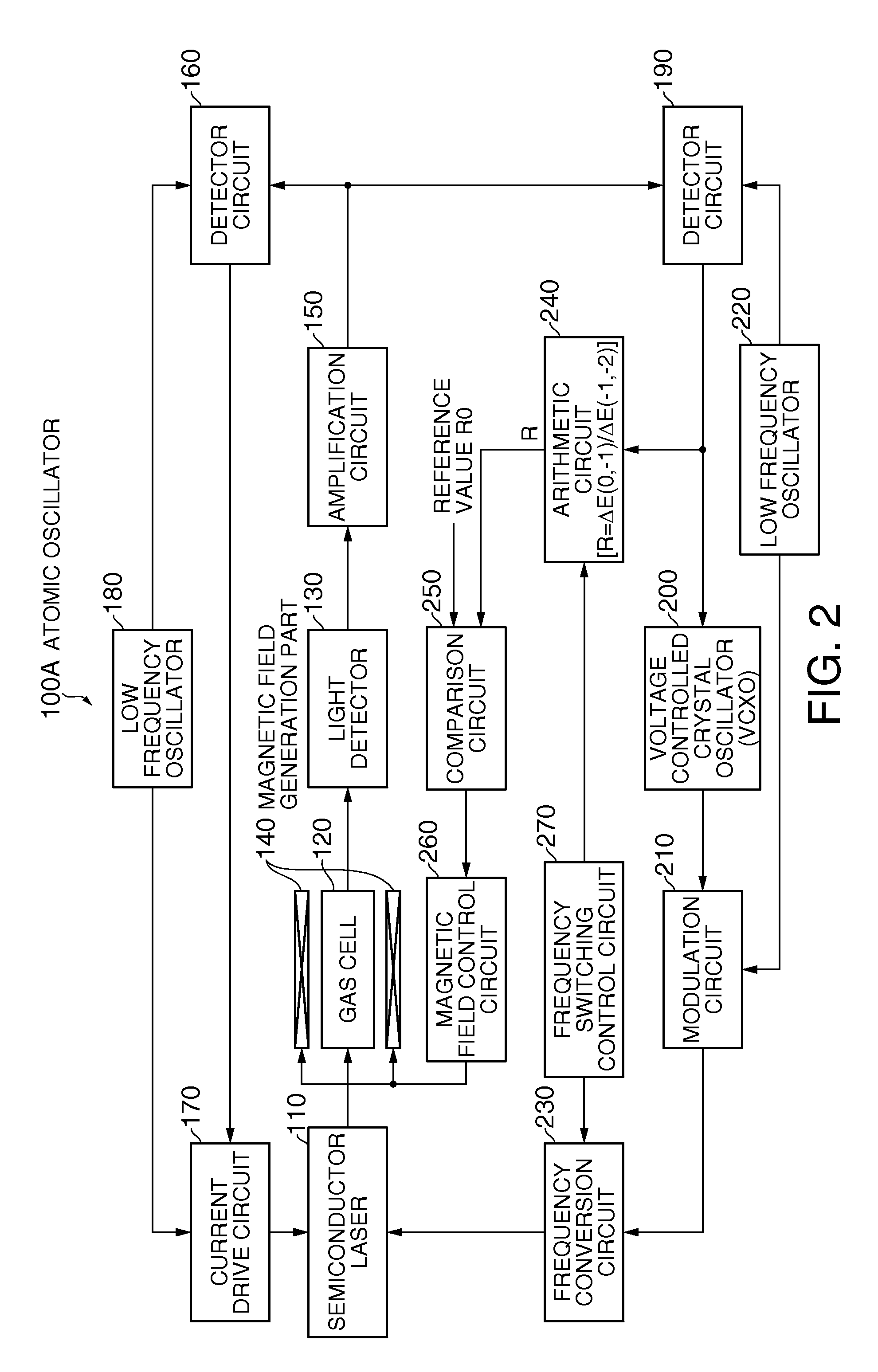
[0053]FIG. 2 is a view showing a structure of an atomic oscillator of a first embodiment.

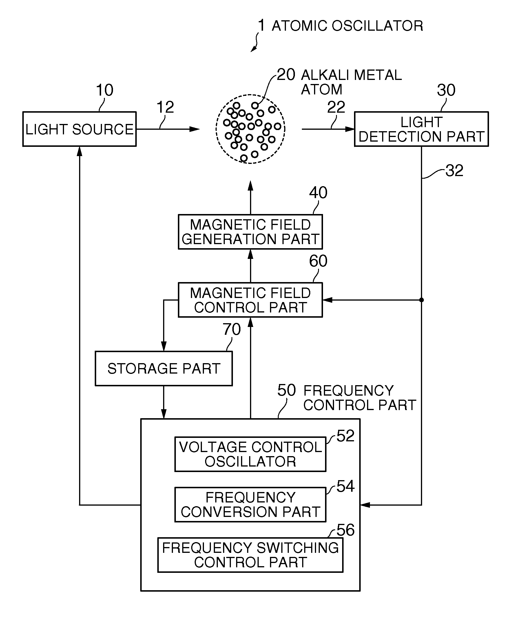
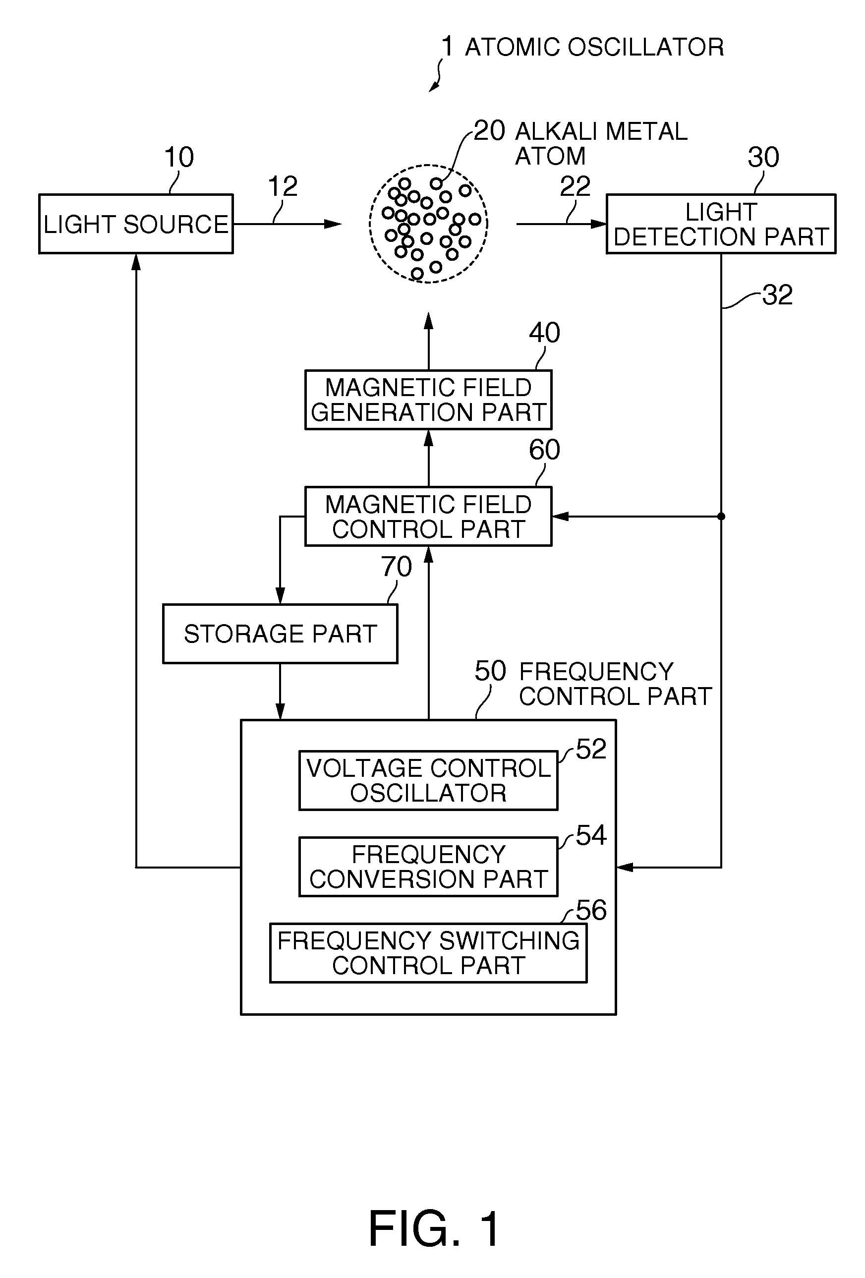
[0054]As shown in FIG. 2, an atomic oscillator 100A of the first embodiment includes a semiconductor laser 110, a gas cell 120, a light detector 130, a magnetic field generation part 140, an amplification circuit 150, a detector circuit 160, a current drive circuit 170, a low frequency oscillator 180, a detector circuit 190, a voltage controlled crystal oscillator (VCXO) 200, a modulation circuit 210, a low frequency oscillator 220, a frequency conversion circuit 230, an arithmetic circuit 240, a comparison circuit 250, a magnetic field control circuit 260 and a frequency switching control circuit 270.

[0055]The semiconductor laser 110 generates plural lights different in frequency from each other and irradiates the lights to the gas cell 120. Specifically, control is performed by a drive current outputted by the current drive circuit 170 so that the center wavelength λ0 (cent...

second embodiment

(2) Second Embodiment

[0095]FIG. 11 is a view showing a relation between magnetic flux and ΔE(−1,−2), ΔE(0,−1), ΔE(+1,0) when frequency f12(0,0), f12(−1,−1), f12(−2,−2) corresponding to ΔE12 for each of (m,m′) =(0,0), (−1,−1) and (−2,−2) is in the relation of FIG. 5. In FIG. 11, the lateral axis indicates the magnetic flux density, and the vertical axis indicates the magnitude of the energy. Besides, ΔE(−1,−2), ΔE(0,−1) and ΔE(+1,0) are respectively indicated by a solid line, a broken line and an alternate long and short dash line.

[0096]As shown in FIG. 11, all of ΔE(−1,−2), ΔE(0,−1) and ΔE(+1,0) monotonically increase with respect to the magnetic flux density. Accordingly, when the intensity of the magnetic field is uniquely determined for anyone of ΔE(−1,−2), ΔE(0,−1) and ΔE(+1,0). That is, when any one of ΔE(−1,−2), ΔE(0,−1) and ΔE(+1,0) is obtained at a specified time, since the intensity of the magnetic field at that time is known, feedback control can be performed so that the i...

third embodiment

(3) Third Embodiment

[0114]In the atomic oscillator 100A of the first embodiment, the frequency conversion rate of the frequency conversion circuit 230 is switched at the constant timing irrespective of the state of the present magnetic field, and the adjustment of the magnetic field intensity is performed at the constant period. On the other hand, in the third embodiment, the timing when the frequency conversion rate of the frequency conversion circuit 230 is switched is changed according to the state of the magnetic field. Specifically, the adjustment period of the magnetic field intensity is changed according to the change of the magnetic field intensity.

[0115]FIG. 13 is a view showing a structure of an atomic oscillator of the third embodiment. In FIG. 13, the same structure as that of FIG. 2 is denoted by the same reference numeral, and its description is omitted or simplified.

[0116]As shown in FIG. 13, in an atomic oscillator 100D of the third embodiment, a history information ...


PUM


Abstract

An atomic oscillator, attention is paid to the fact that the degree of change of the energy difference between the two ground levels of the alkali metal atom with respect to the change of the magnetic field intensity is specific to each of the magnetic quantum numbers, a resonant light pair to cause a transition between the two ground levels corresponding to each of the plural magnetic quantum numbers is sequentially generated, plural pieces of profile information capable of specifying the energy difference between the two ground levels corresponding to each of the magnetic quantum numbers are sequentially acquired based on the detection signal, the change amount of the magnetic field intensity is specified based on the acquired plural pieces of profile information, and the control is performed so that the intensity of the magnetic field becomes constant.

Description

BACKGROUND[0001]1. Technical Field[0002]The present invention relates to an atomic oscillator.[0003]2. Related Art[0004]An atomic oscillator based on an EIT (Electromagnetically Induced Transparency) system (also called a CPT (Coherent Population Trapping) system) is an oscillator using a phenomenon in which when two kinds of resonant lights having coherency and having specific wavelengths (frequencies) different from each other are simultaneously irradiated to an alkali metal atom, absorption of the resonant lights is stopped.[0005]As shown in FIG. 14, it is known that the interaction mechanism between the alkali metal atom and the two kinds of resonant lights can be explained in a Λ-type three-level model. The alkali metal atom has two ground levels, and when resonant light 1 having a frequency corresponding to an energy difference between the ground level 1 and the excited level or resonant light 2 having a frequency corresponding to an energy difference between the ground level ...

Claims


Application Information

Patent Timeline
Patent Type & Authority Patents(United States)
IPC IPC(8): H03L7/26
CPCG04F5/145H03B17/00
Inventor AOYAMA, TAKU
Owner MICROCHIP TECH INC
Why Eureka
Try Eureka