
Fluid dispensing system

a technology of fluid dispensing system and fluid, which is applied in the direction of liquid handling, laboratory glassware, instruments, etc., can solve the problems of low viscosity fluids that may leak, unwanted contact with other areas, and unsatisfactory finished products

Active Publication Date: 2012-09-04
PHILIP FISHMAN CORP
View PDF19 Cites 13 Cited by
  • Summary
  • Abstract
  • Description
  • Claims
  • Application Information

AI Technical Summary

Benefits of technology

The system achieves accurate and precise dispensing of fluids by dynamically adjusting the backoff distance as the syringe is depleted, maintaining consistent dot or bead sizes across different fluid viscosities and syringe volumes, reducing leakage and improving the quality of dispensed products.

Problems solved by technology

Dispensing consistent, controllable, and accurate amounts of fluids of varying viscosities remains a long standing issue for manufacturers and others where an efficient, accurate and precise amount of liquid dispensed supports a high quality product.
If, for example, too little adhesive is dispensed the assembly may not have the structural integrity of a quality product; too great a dot or bead and the excess may ooze and make unwanted contact with other areas and / or present an unsightly finished product.
In addition, low viscosity fluids may leak after the dot or bead is dispensed.
These systems often leak and lose both air and vacuum (negative) pressure resulting in imprecise and inaccurate dots and beads.
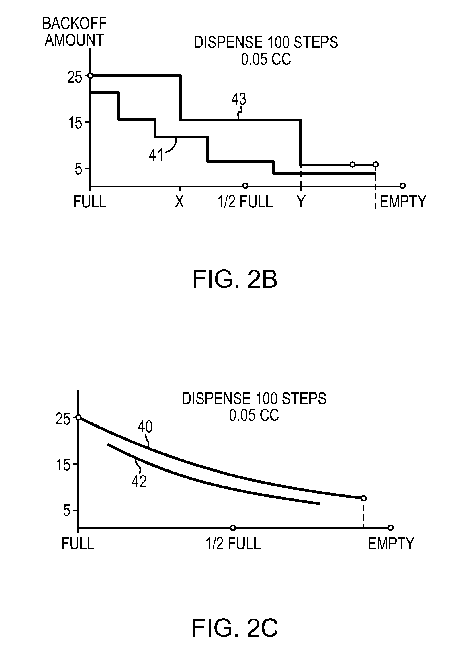
A predetermined backoff distance, however, does not account for the reduction of the fluid and the increase of the air space behind the piston in the syringe, as the fluid is dispensed.
It has been found that inaccurate, imprecise amounts of fluid are delivered as the syringe fluid is depleted since the predetermined distance results in a different pressure change as the air space behind the piston changes.

Method used


Image

  • Fluid dispensing system
  • Fluid dispensing system
  • Fluid dispensing system

Examples


Embodiment Construction

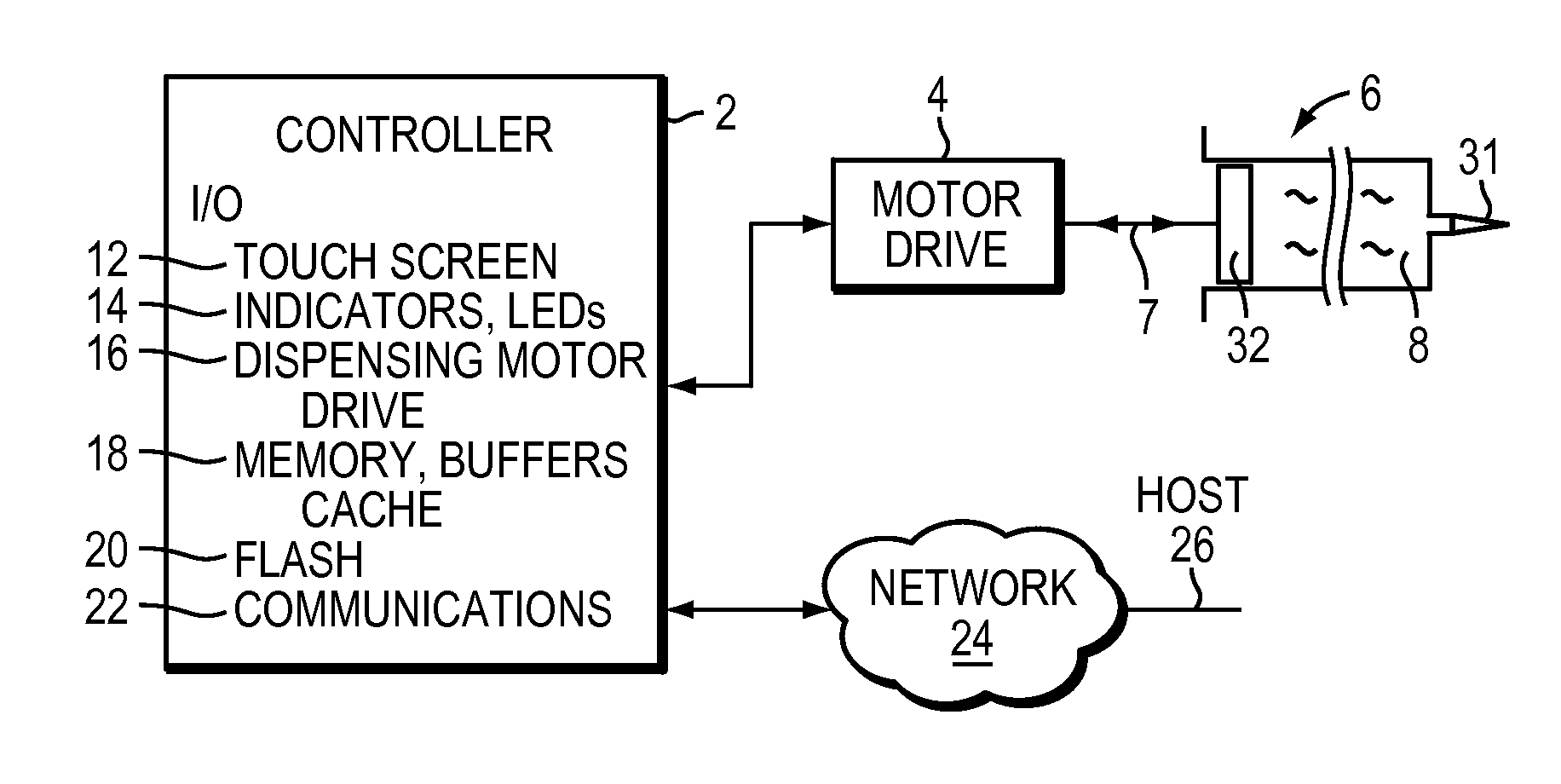
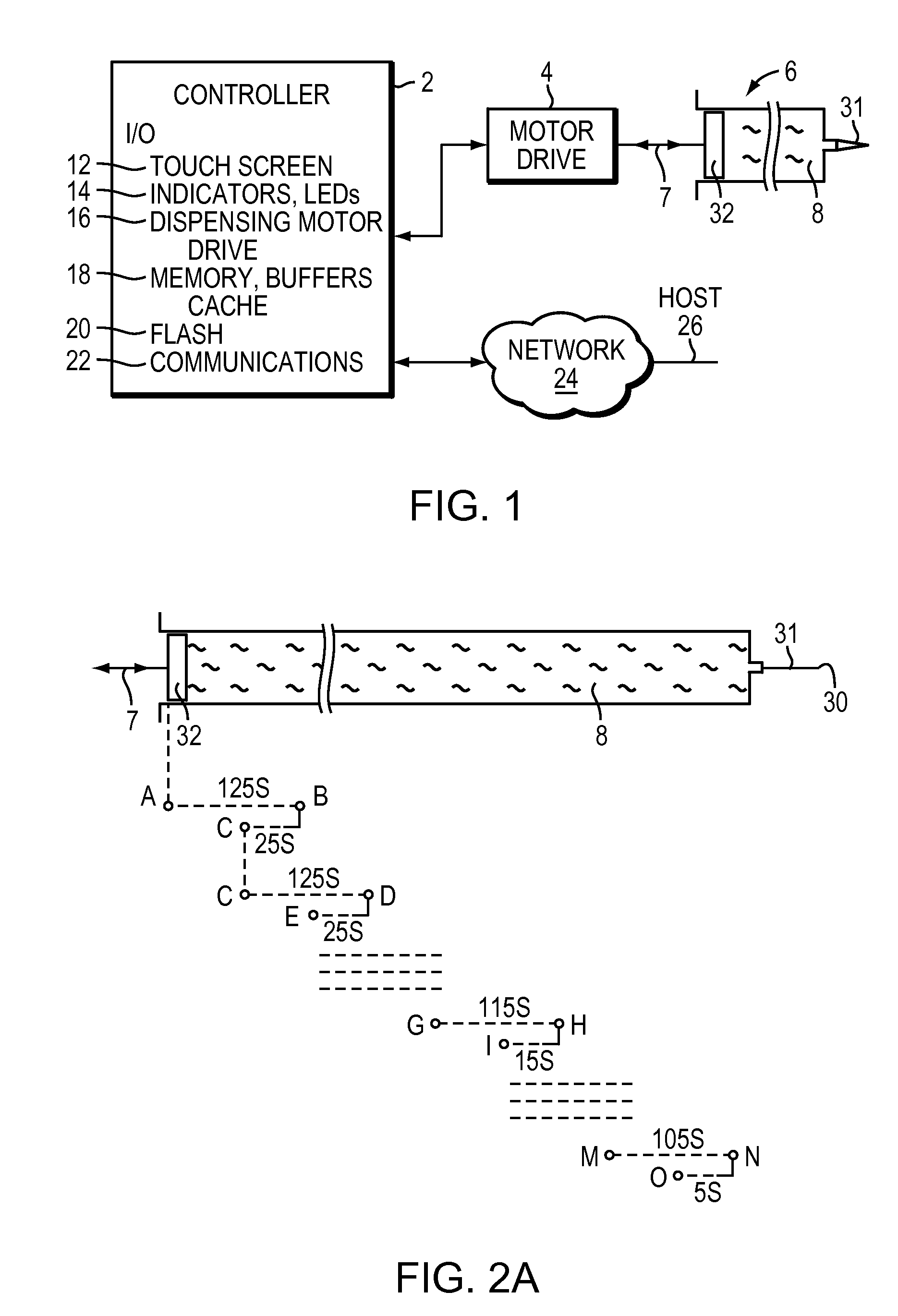
[0023]FIG. 1 illustrates a dispensing system with a controller 2 and a dispensing unit 4 driving a syringe 6 carrying a liquid 8 for dispensing. The dispensing unit 4 may include a hand held device or a fixed device as part of a work station (not shown). The dispensing unit may include a motor, e.g., a stepping motor with accompanying electronics wherein the stepping motor may operate the syringe in both directions 7. The stepping motor typically will be controlled by an I / O (Input / Output) interface 10 in the controller 2.

[0024]Illustratively a stepping motor system is discussed herein, but an analog servo-type system with an attached or integral phase or other type distance traveled encoder may be used with the appropriate electronics in other applications.

[0025]The controller 2 may include a human interface, such as a touch screen 12 or other known connected or wireless means for inputting commands and displaying status, information, etc. For example a keypad or full keyboard may ...


PUM


Abstract

A fluid dispenser is disclosed where a backoff distance is determined and implemented to prevent leakage while dispensing sequentially an accurate, precise amount of fluid substantially independent of the fluid remaining in a syringe-type dispenser. The fluid characteristics of the fluid, e.g. viscosity, surface tension, etc. affect the backoff distance that may be determined heuristically for fluid type, amount of fluid remaining in the syringe and amount to be dispensed. Once the fluid characteristics are known, the dispensing may be accomplished automatically with a processor loading new drive and backoff steps to a motor controller.

Description

BACKGROUND OF THE INVENTION[0001]1. Field of the Invention[0002]The present invention is related to fluid dispensing systems and methods associated with their use. More particularly, the present invention relates to those applications of a wide range of fluids with different viscosities where preciseness and accuracy of the amount of fluid dispensed is important.[0003]2. Background Information[0004]Dispensing consistent, controllable, and accurate amounts of fluids of varying viscosities remains a long standing issue for manufacturers and others where an efficient, accurate and precise amount of liquid dispensed supports a high quality product.[0005]Herein “accurate” refers to how exact is an amount dispensed, and “precise” refers to how repeatable is the amount dispensed.[0006]Herein the term “dot” or “bead” refers to the quantity of fluid dispensed, and “fluid” refers to liquids or suspensions that react as do liquids.[0007]In a product manufacturing environment it is important to...

Claims


Application Information

Patent Timeline
Patent Type & Authority Patents(United States)
IPC IPC(8): B67D1/00B65D88/54B65D5/72
CPCB05C17/00593G01F11/029B05C17/014B05C17/0103
Inventor BEEBE, W. SCOTT
Owner PHILIP FISHMAN CORP
Learn More