Apparatus for harvesting energy from flow-induced oscillations and method for the same

a technology of flow-induced oscillation and apparatus, applied in the direction of electric generator control, machines/engines, sustainable buildings, etc., can solve the problems of low cost-effectiveness at regimes with a lower power output, limited efficiency at wide range of flow velocity, and inability to efficiently adjust to flow velocity changes

Inactive Publication Date: 2012-09-04
KAPLAN A MORRIS
View PDF33 Cites 28 Cited by
  • Summary
  • Abstract
  • Description
  • Claims
  • Application Information

AI Technical Summary

Benefits of technology

[0024]An arbitrary number of electricity generating cells can be connected into a single circuit, either in-series or in-parallel, to increase an overall power output. Such combinations can be manufactured using MEMS technology, with series of cells being micro-fabricated by a batch-fabrication or micromachining, including integration of the rectifying circuitry and magnetic field sources into the same wafer. The future ‘generators-on-chip’ and ‘generating-panels’ concepts can be developed by this technology. The generating panels may include more than one layer of various generating cells. This can benefit the total generator output by harvesting energy flow at different locations of the flow stream.
[0028]For example, hundreds or thousands of small generating cells, implemented as roof panels, can become a virtually maintenance-free source of electrical power, making it a much better alternative to expensive solar panels. Unlike the previously reported power generators, the disclosure is capable to operate under wide range of the flow condition. It is capable to operate both at low and very high flow velocities, without any additional damage-preventive equipment. The disclosure does not include any massive elements which can be dangerous when detached if the device fails under extreme conditions. The disclosure does not require any rotating, friction, grinding parts or flexible membranes to provide a quiet, virtually maintenance-free, operation.

Problems solved by technology

Although the turbine-based wind generators are, in general, effective in certain conditions, they have limitations resulting from typical requirements of large open spaces (consistently high-speed winds), infrastructure development and large initial capital costs.
One if the main disadvantages of turbine-based wind generators is a limited efficiency at wide range of flow velocities, specifically, low cost-effectiveness at regimes with a lower power output and lack of the efficient adjustment to flow velocity changes.
Another frequent objection to large wind turbines is that they take a lot of space and often considered to be an eyesore.
However, the use of small wind generators (typically less that 10 kilowatts peak power) has generally been limited.
The small wind generators currently suffer from substantial drawbacks that prevent their widespread adoption.
Such limitations are the cost per produced energy, low energy capture, conversion and efficiency.
Towers might also interfere with aviation and / or being visually obtrusive.
Other disadvantages include noisy operation, rotor turbulence sensitivity and possible over-speed failures.
While such generators can provide sufficient energy for small applications, they are not optimized for efficient conversion of energy available in various flows of gases or fluids.
This mass needs a special vibration assembly and, in some cases, a source of instability at the oscillation onset.
It limits the span of possible oscillation frequencies and / or may damp down the desired oscillation frequencies for certain flow characteristics.
Moreover, in all proposed generators the weight of the vibrating element restricts the allowed transducer geometry, resulting in a limited range of oscillating frequencies needed for efficient energy conversion.
Accordingly, previously disclosed vibration-based power generators are not optimized to couple the available energy of the various flows into the vibration assembly, which limits the conversion efficiency.
Furthermore, all mentioned proposals for small wind / hydro generators are not always satisfactory due to the design complexities, manufacturing cost, need for a complex mounting / control structures, high maintenance cost and low efficiency in energy production at various flow velocities.
In particular, the use of mentioned flexible ribbon (membrane that fixed at two or more points) is prone to insufficient power generation due to limited production of vibrations under various conditions, restriction to high flow speeds, temperature and humidity changes, requirements for real-time adjustments, etc.
Vibration-based electro-mechanical converters are facing another problem of efficient rectifying of the generated alternating current (AC).

Method used


Image

  • Apparatus for harvesting energy from flow-induced oscillations and method for the same
  • Apparatus for harvesting energy from flow-induced oscillations and method for the same
  • Apparatus for harvesting energy from flow-induced oscillations and method for the same

Examples


Embodiment Construction

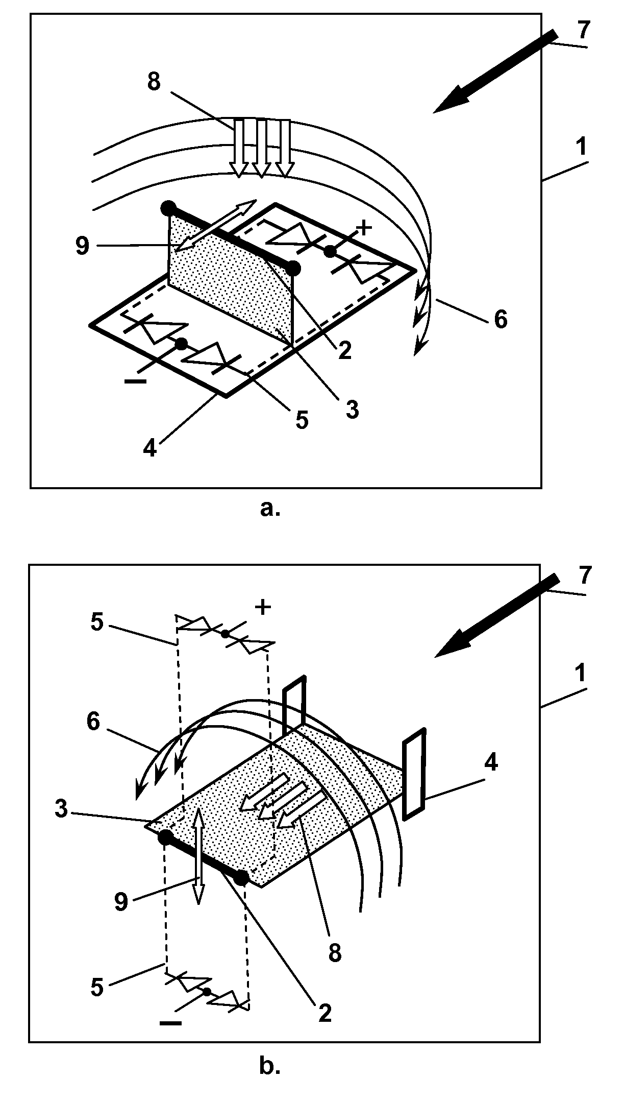
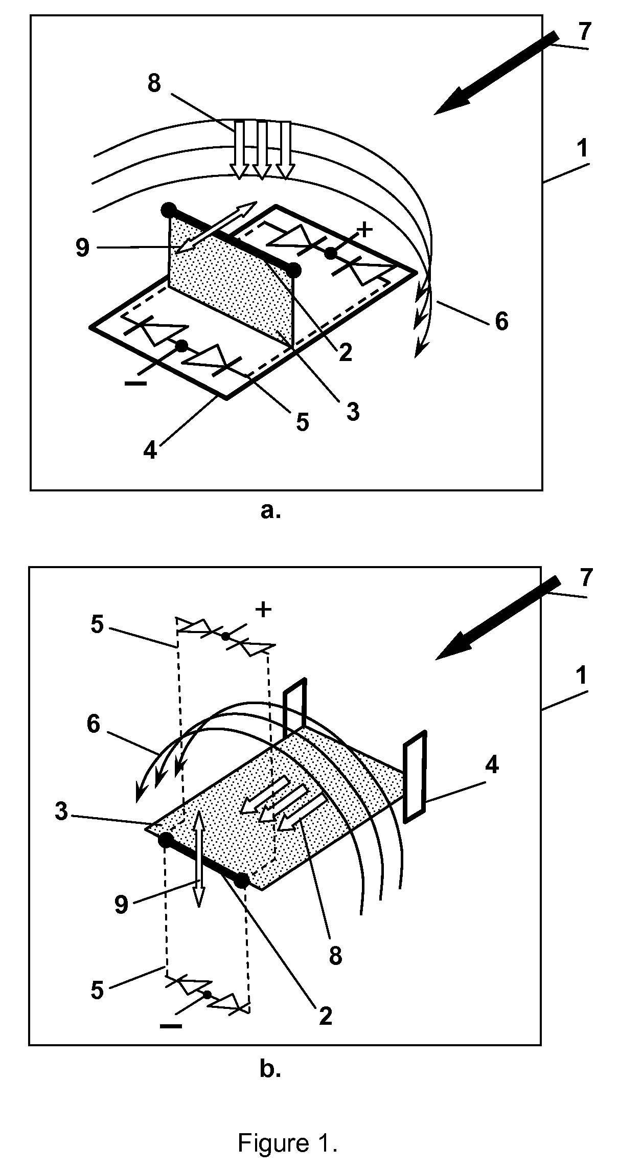
[0037]An electrical generator includes at least one electrical conductive element and at least one magnetic field source in the presence of the external flow. The conductive element is monolithically integrated with an elastic element and configured to move with the elastic element. The elastic element is attached to the base at least at one point. When the flow does not impinge on the elastic element, the elastic element and the conductive element are maintained in a neutral position at the base. The flow impinges on the elastic element causing a displacement of the elastic element with integrated conductive element, producing electricity in the proximity of the magnetic field.

[0038]The preferred embodiment of the generator is described below, but it should be clearly understood that the principles of the invention are not limited to any particular embodiment of generator described herein. It will be apparent to one skilled in the art that the present disclosure may be practiced wi...


PUM


Abstract

A device and method for harvesting electrical power from kinetic energy of a flow. The electricity generator includes a vibration assembly and magnetic field source. The external gas or liquid flow causes a vibration of the assembly with an integrated conductive element, producing electricity in proximity of a magnetic field. The vibrating assembly has a set of resonant frequencies that correspond to a set of the frequencies of the flow vortices within a predetermined range of the external flow velocities. An arbitrary number of adjustable generators can be connected into a single circuit, either in-series or in-parallel, to increase an overall power output. It is capable to operate under wide range of flow characteristics and can serve as a virtually maintenance-free source of electrical power.

Description

FIELD OF INVENTION[0001]This invention relates to electricity generation from the oscillations of an arbitrary structure in the presence of a flow of different types.BACKGROUND OF THE INVENTION[0002]The invention is related to conversion of kinetic energy, which is present in various flows, such as airflows, water flows, tides, etc., into electricity. This disclosure describes various embodiments of a novel energy converter that efficiently utilizes oscillations induced by different types of a flow, in order to generate electricity or other types of energy.[0003]The flow energy of water or wind has been utilized by mankind for centuries. The kinetic energy of the flow can be converted into rotating or oscillating movements of the affected device, where energy can further be harvested by different means.[0004]Modern wind-powered and hydro-powered generators that based on propeller, rotor, turbine or rotating airfoil became reliable and widespread energy sources and their implementati...

Claims


Application Information

Patent Timeline
Patent Type & Authority Patents(United States)
IPC IPC(8): F03D5/00H02K35/00
CPCF03B17/06F03D5/06F03G7/08F03B13/182F05B2250/41Y02E10/28Y02E10/70Y02E10/725F05B2210/16Y02B10/30Y02B10/70Y02E10/38Y02E10/30Y02E10/20Y02E10/72
Inventor KAPLAN, A. MORRIS
Owner KAPLAN A MORRIS
Why Eureka
Try Eureka