Intuitive multiple degrees of freedom portable control device

a control device and intuitive technology, applied in the field of control devices, can solve the problems of difficult to use, complex implementation of controllers constructed according to this approach, and impose limitations on the design of human machine interfaces (hmi), and achieve the effect of effective control of the vehicle or mechanism and little learning effor

Active Publication Date: 2012-09-04
MEASUREMENT SYST
View PDF4 Cites 109 Cited by
  • Summary
  • Abstract
  • Description
  • Claims
  • Application Information

AI Technical Summary

Problems solved by technology

Conventional isotonic or displacement type of hand controllers such as joysticks and yokes rely on a cumbersome kinematic mechanism to restrict a human operator's three dimensional movements into a confined space.
Control devices employing these sensors make indirect measurements of the operator's movements and impose limitations on the design of a human machine interface (HMI).
Controllers constructed according to this approach are complex to implement and awkward to use.
In addition, using such a controller is not intuitive for the user; this lengthens the user's learning curve.
Due to inherent kinematic requirements, the mounting location and alignment of the sensors in such devices are often restricted, for example, to be at or near a pivot axis.
Design flexibility and configurability are therefore limited.
It is cumbersome to remove such equipment.
In addition, when a conventional control device is mounted in a moving vehicle, the motion sensors therein may be susceptible to fictitious forces.
Furthermore, these devices generally contain moving components that are subject to friction, backlash, binding, and deterioration over time and under changing environmental conditions, which thus impact their long-term reliability.
Their size and weight often make such devices not suitable for portable or wearable applications.

Method used


Image

  • Intuitive multiple degrees of freedom portable control device
  • Intuitive multiple degrees of freedom portable control device
  • Intuitive multiple degrees of freedom portable control device

Examples


Embodiment Construction

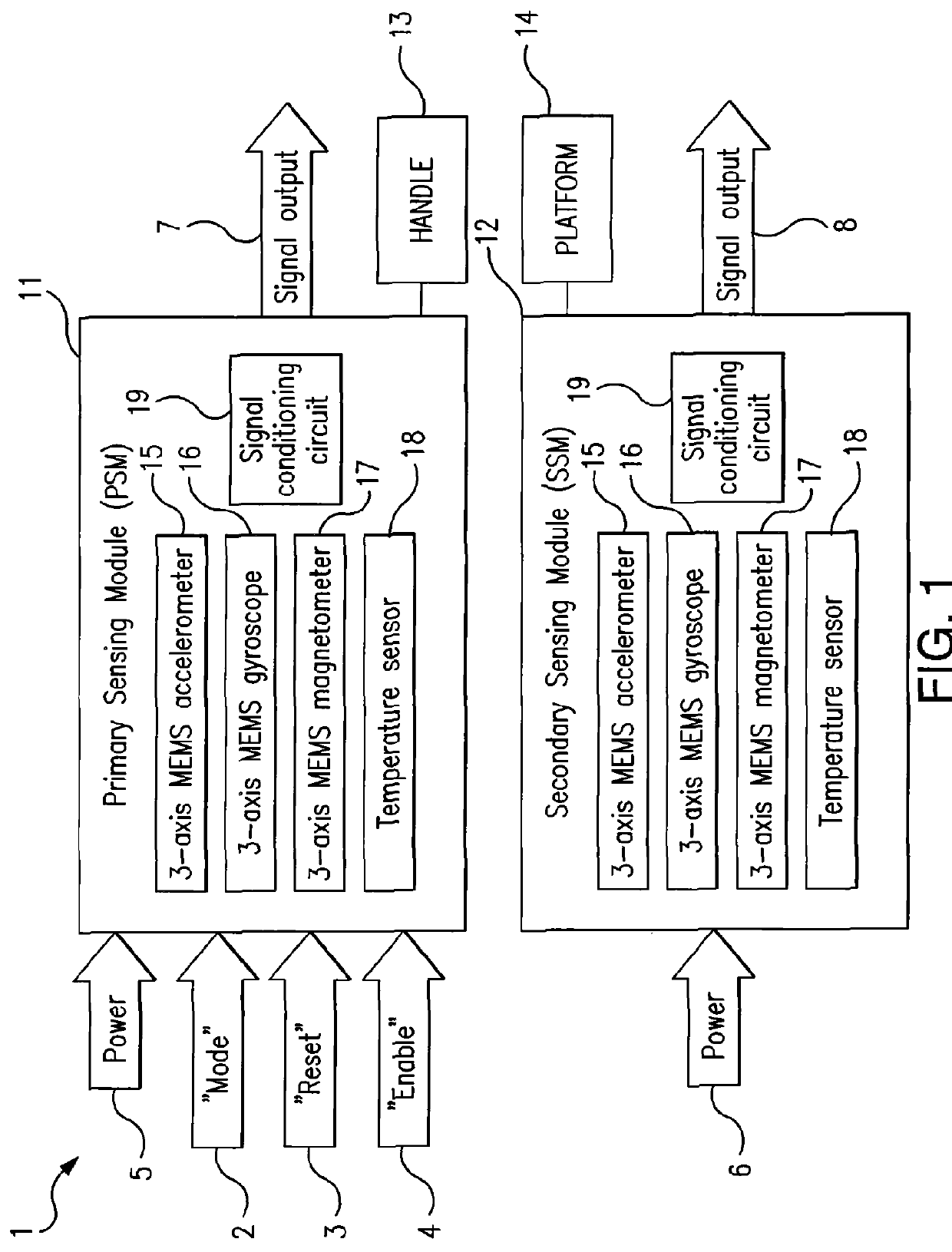
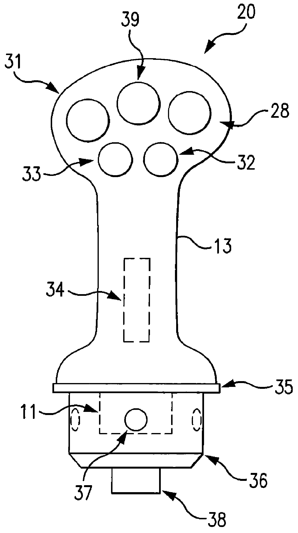
[0026]A control device according to the present disclosure is a displacement type control device operated by a human hand or hands, or a body segment when a human hand is not accessible. The device does not have conventional movement sensors and does not require a kinematic mechanism. Direct motion measurement is achieved by employing a combination of MEMS (micro-electromechanical systems) sensors arranged into modules, as detailed below.

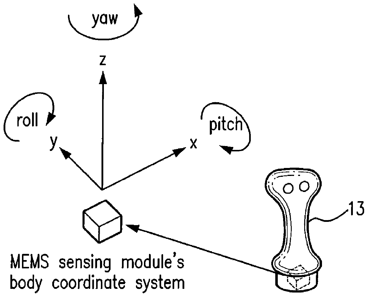
[0027]Each MEMS sensing module contains a three-axis MEMS accelerometer, a three-axis MEMS gyroscope and a three-axis MEMS magnetometer in a compact package having a volume less than 0.2 cubic inch. Each module thus has the capability to measure acceleration, angular rotation rate and geomagnetic field in the sensing module's body coordinate system with respect to Earth. This capability provides a total of six degrees of freedom (DOFs), a significant advantage in terms of form factor over conventional electronic sensors.

[0028]In addition, the MEMS s...


PUM


Abstract

A control device for a vehicle or mechanism includes a portable displacement controller which permits a non-technical user to achieve effective control of the vehicle or mechanism, by moving the portable displacement controller intuitively with little learning effort. A first sensing device, attached to the displacement controller, detects the user's controlling motion. A second sensing device, attached to the object being controlled, detects motion thereof. An interface device receives signals from the sensing devices, processes those signals to determine relative motion of the controlling motion and the object's motion and outputs a control signal in accordance with the processed signals. The sensing devices each detect motion in six degrees of freedom; the sensing devices each include a three-axis accelerometer, a three-axis gyroscope, and a three-axis magnetometer. In specific embodiments, the accelerometers, gyroscopes, and magnetometers include micro-electromechanical system (MEMS) devices.

Description

CROSS-REFERENCE TO RELATED APPLICATIONS[0001]This application claims the priority benefit of provisional U.S. Application No. 61 / 309,886 filed Mar. 3, 2010, the entire disclosure of which is incorporated herein by reference.FIELD OF THE DISCLOSURE[0002]This disclosure relates to control devices, and more particularly to portable devices for controlling other devices capable of movement with multiple degrees of freedom (including but not limited to vehicles).BACKGROUND OF THE DISCLOSURE[0003]Conventional isotonic or displacement type of hand controllers such as joysticks and yokes rely on a cumbersome kinematic mechanism to restrict a human operator's three dimensional movements into a confined space. Mechanical linkages such as shafts, gears, bearings and springs, etc. are employed as necessary to transfer motions from the human operator to the electronic sensors attached to the mechanism. Widely used sensors such as potentiometers, transformers, Hall effect sensors, magneto-resisti...

Claims


Application Information

Patent Timeline
Patent Type & Authority Patents(United States)
IPC IPC(8): G09B21/00
CPCG06F3/0346A63F2300/105G05D1/0808G05D1/0016
Inventor CAI, STEVENLEBLANC, PAUL J.ECSEDY, THOMAS R.YOHO, LESLIE W.
Owner MEASUREMENT SYST
Why Eureka
Try Eureka