
Near-field recording device having heating mechanism positioned near a trailing side of a magnetic pole

a near-field recording and heating mechanism technology, applied in the field of magnetic recording methods and magnetic recording apparatuses, can solve the problems of reducing the intensity of recording magnetic field, restricting the increase of recording magnetic field intensity, and causing thermal instability of grains

Active Publication Date: 2012-09-11
WESTERN DIGITAL TECH INC
View PDF19 Cites 16 Cited by
  • Summary
  • Abstract
  • Description
  • Claims
  • Application Information

AI Technical Summary

Benefits of technology

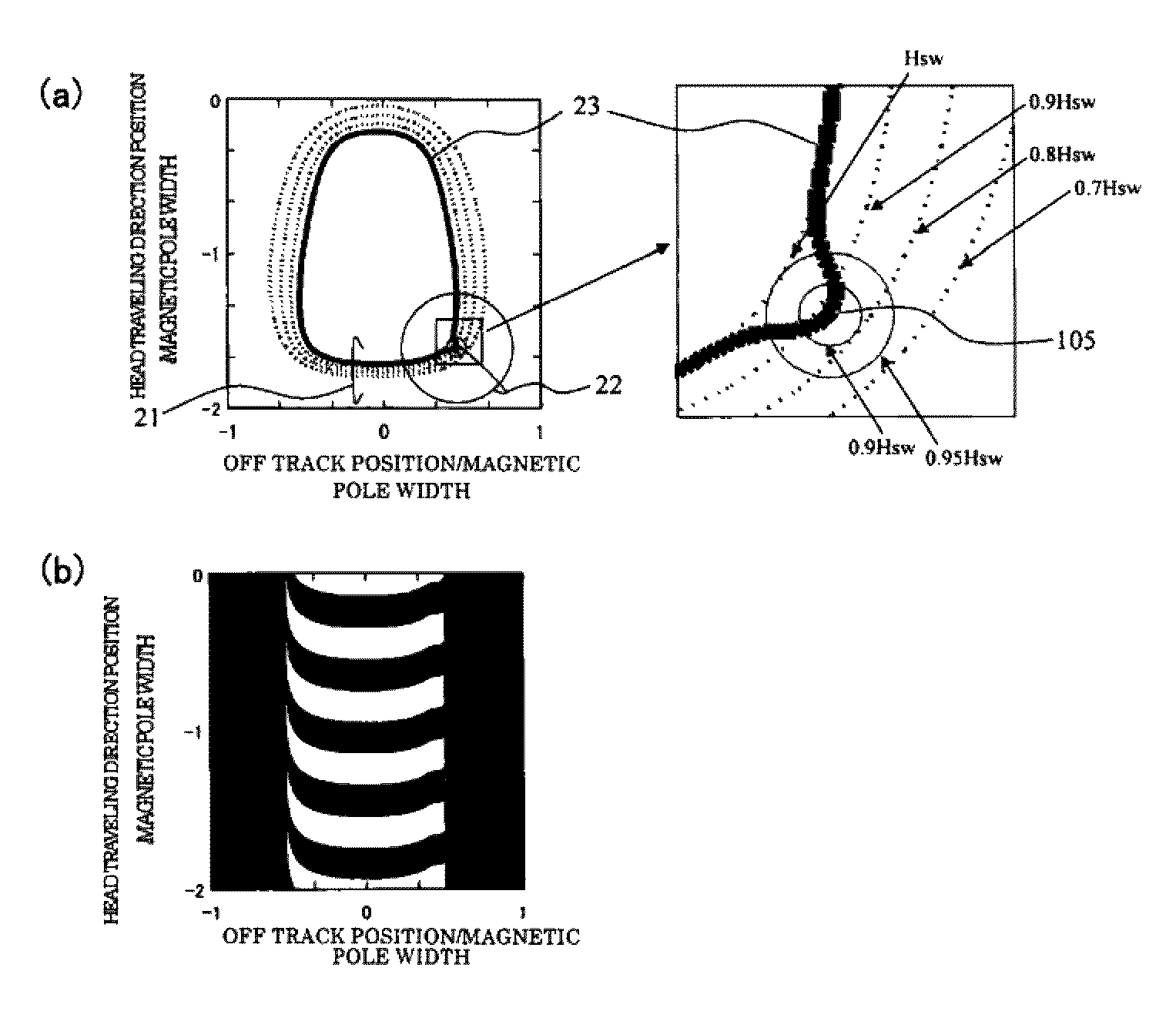
This approach enables high-density magnetic recording by reducing magnetization transition curvature, enhancing readback signal resolution, and maintaining thermal stability and recording capacity, effectively addressing the trilemma of grain size, track width, and signal quality.

Problems solved by technology

Although the media noise can be reduced by micronizing the magnetic crystal grains, a problem occurs in that the grains become thermally unstable.
However, the narrowing of the recording core width reduces the recording magnetic field intensity.
Besides, there is a limit in increase of the recording magnetic field intensity by the optimization of the recording magnetic pole material and the structure of the recording head.
When the recording magnetic field intensity is insufficient as compared with the switching magnetic field of the medium, that is, when the recording capacity is lowered, part of bits cannot be inverted, and the signal quality is reduced.
Thus, it is difficult to micronize the crystal grains of the recording medium and to narrow the track width of the recording head while the thermal stability of the recording medium and the recording capacity of the recording head are maintained.
This is because, when the spot size of light is excessively larger than the recording width, a track adjacent to the recorded track is also heated, and the thermal stability is degraded.
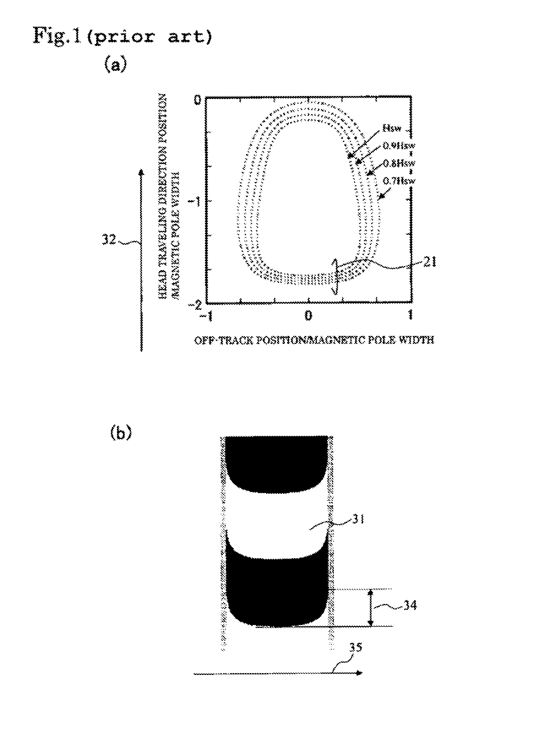
This is because when a recording pattern which does not have a recording system, there is a problem that the transition shape of the recording pattern recorded on the recording medium by the rectangular shape is reproduced by a giant magnetoresistive (GMR) head or a tunneling magnetoresistive (TMR) head, the transition width between bits appear large, and the readback signal resolution is reduced.
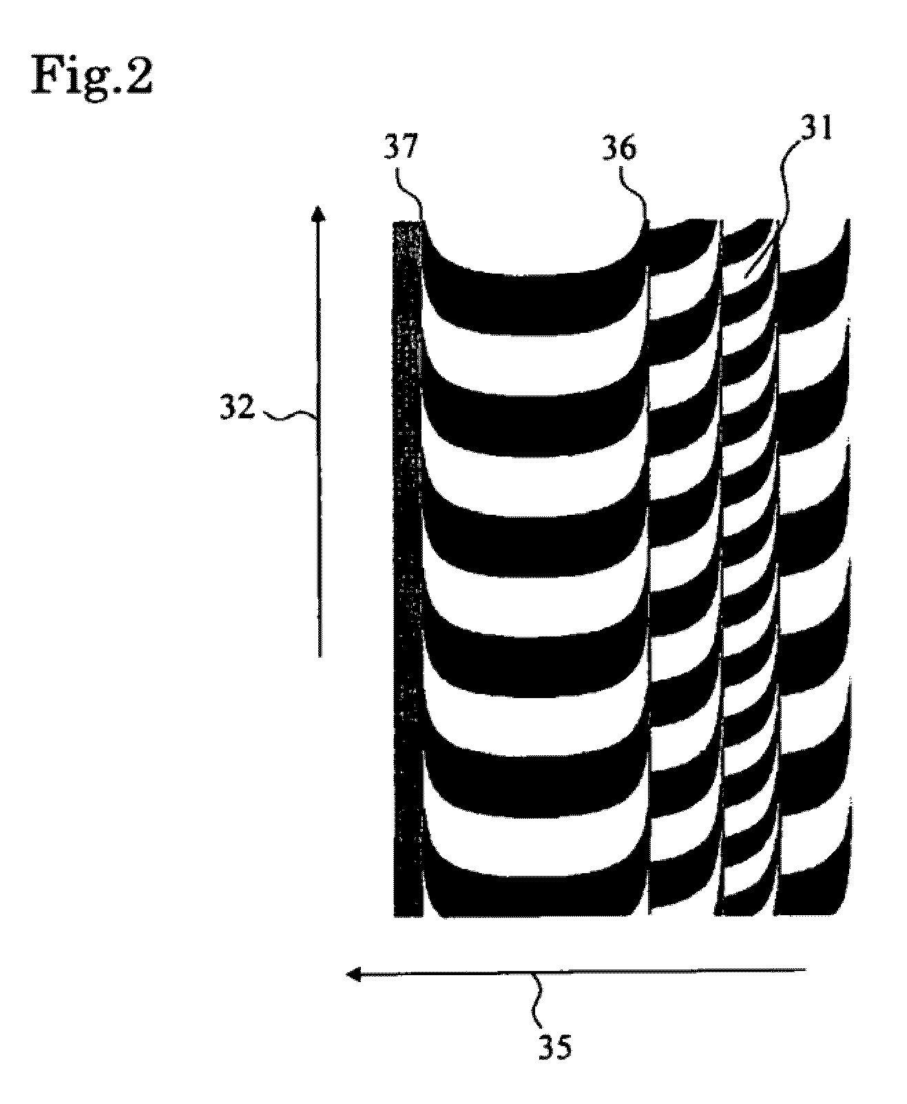
However, in current recording systems, there is a problem that the transition shape of the recording pattern recorded on the recording medium by the recording head is curved at a track edge as compared with the track center.

Method used


Image

  • Near-field recording device having heating mechanism positioned near a trailing side of a magnetic pole
  • Near-field recording device having heating mechanism positioned near a trailing side of a magnetic pole
  • Near-field recording device having heating mechanism positioned near a trailing side of a magnetic pole

Examples


embodiment 1

[0047]FIG. 4 is a view showing a structural example of a magnetic recording apparatus of the invention. In general, one or several magnetic disks 15 are mounted in a drive of the magnetic recording apparatus. The magnetic disk 15 of this embodiment is a disk for perpendicular magnetic recording including a soft magnetic ground layer and a perpendicular magnetic recording layer, and is rotated and driven in a direction of an arrow 10. As shown in an enlarged view in (a), a magnetic head 12 at the rear end of a magnetic head slider 11, fixed to a tip of a carriage 13, accesses an arbitrary track by a voice coil motor 14, and records and reproduces information on the magnetic disk (medium). An enlarged view (b) is a schematic view seen from a medium opposite surface and showing a stricture of a recording head 101 to perform recording and a reproducing head 16 to perform reproduction. The recording head 101 is a single magnetic pole recording head for perpendicular magnetic recording an...

embodiment 2

[0063]Since the effect of reduction of the magnetization transition curvature amount of the recording pattern according to the invention is obtained by reducing the switching magnetic field at the track edge side of the recording pattern as compared with the switching magnetic field at the track center, the invention, according to one embodiment, is effective also in normal heat assist recording in which the switching magnetic field at the time of non-heating is higher than the magnetic field intensity of the magnetic pole, and recording can not be performed unless heat assist is used.

[0064]Hereinafter, with respect to another embodiment of the invention, a result of study obtained by calculator simulation is described. Structures of a recording head and a magnetic recording medium are the same as those of Embodiment 1. However, the switching magnetic field of the recording medium is 18 kOe and is higher than the applied magnetic field of a magnetic pole, and a pattern cannot be rec...

embodiment 3

[0068]Next, an embodiment in which the invention is applied to a shingle recording system will be described. FIG. 15 is a schematic view in which a part of a magnetic head of this embodiment is seen from an air bearing surface. This is different from Embodiment 1 and Embodiment 2 in that a conductive light scattering body 103 to generate near-field light is arranged only at a track edge of one side.

[0069]As in Embodiment 1, when a medium is used in which the switching magnetic field of the recording medium at the time of non-heating is low as compared with the recording magnetic field of a main magnetic pole, the transition curvature amount of an edge at a heating side is reduced as compared with that at the time of non-heating. Thus, when the edge at the heating side is made a remaining edge, a recording pattern in which the transition curvature amount is reduced can be formed as shown in FIG. 16, according to one embodiment.

[0070]As in Embodiment 2, when a medium is used in which ...


PUM

PropertyMeasurementUnit
lengthaaaaaaaaaa
recording magnetic fieldaaaaaaaaaa
widthaaaaaaaaaa

Abstract

One purpose of the invention according to one embodiment is to provide a magnetic recording apparatus of high recording density in which magnetization transition curvature amount of a recording pattern is small. In one embodiment, the center of a heating area is arranged at a track edge side of a recording pattern as compared with the width-direction center position of a main magnetic pole of a recording head, and a recording magnetic field is applied while a medium is locally heated at the time of signal recording. A switching magnetic field of the medium is locally reduced by heating, so that a line where the switching magnetic field of the medium is equal to the recording magnetic field from the head approaches the heating center position, and a desired recording pattern in which the transition curvature amount is reduced can be realized. Other systems and methods are also presented.

Description

RELATED APPLICATIONS[0001]The present application claims the priority of a Japanese patent application filed Aug. 6, 2008 under application number 2008-202574, which is incorporated herein by reference.FIELD OF THE INVENTION[0002]The present invention relates to a magnetic recording method and a magnetic recording apparatus, and particularly to a magnetic recording apparatus which enables high-density recording by locally heating a recording medium by a heating source and by performing magnetic recording.BACKGROUND OF THE INVENTION[0003]As a device capable of recording large capacity data, a magnetic recording apparatus is a basic technology to support the present high information society. In the magnetic recording apparatus, data on a recording medium is read and written by a magnetic head. In order to increase the recording capacity per unit area of a magnetic disk, it is necessary to raise bit areal recording density. In order to increase the recording density, it is necessary to...

Claims


Application Information

Patent Timeline
Patent Type & Authority Patents(United States)
IPC IPC(8): G11B11/00
CPCG11B5/314G11B5/4866G11B2005/001G11B2005/0021
Inventor HASHIMOTO, MITSUHIROMATSUMOTO, TAKUYAAKAGI, FUMIKOSUZUKI, YOSHIO
Owner WESTERN DIGITAL TECH INC
Learn More