Catheter locator apparatus and method of use

a technology of catheter and locator, which is applied in the direction of catheter, application, instruments, etc., can solve the problems of increased risk factors, time-consuming, and difficult placement of the tip into the duodenum and jejunum, and the inability to solve the problem of enteral feeding. not easy, and the effect of significant complications

Inactive Publication Date: 2012-09-11
AVENT INC
View PDF142 Cites 25 Cited by
  • Summary
  • Abstract
  • Description
  • Claims
  • Application Information

AI Technical Summary

Problems solved by technology

Access to the duodenum and jejunum is possible with longer tubes but placement of the tip into the duodenum and jejunum is more difficult and time consuming and has added risk factors.
However, enteral feeding is not problem free, and significant complications can occur when the tube and feeding is managed by unskilled or untrained individuals or if monitoring is absent or inappropriate.
Most serious is the unintended placement of the catheter during nasal intubation into the cardiovascular system or into the lungs.
However, even X-rays are not necessarily conclusive as to its location.
The natural and continuous movement of the internal organs can make it difficult for the physician interpreting the X-ray to be sure of the actual location of the caudal / distal end of the tube because the movement described can change the position of the catheter over time.
Ultrasound guidance, fluoroscopy and X-ray methodologies are preferred even though they do not always provide an exact determination of the location of the tip or path of the guide wire or catheter.
More expensive and more lime-consuming CT examinations provide the best means of locating not only the tip but also the path of any of the types of catheter described above and others that are located in the body of a patient.
Greater likelihood of unwanted developments can occur when a catheter tip is located in the sub-clavian vein or the cavoatrial junction or in the right atrium.
The effect of inappropriate or less than ideal catheter tip location is shortened survival which clearly is manageable but more serious effects may include thrombosis and phlebitis infections more, particularly pheumothorax infections and, in more serious situations, occlusions.
However, they should be critically checked by X-ray to determine appropriate tip placement even though this is neither a totally satisfactory nor certain method of location checking.

Method used


Image

  • Catheter locator apparatus and method of use
  • Catheter locator apparatus and method of use
  • Catheter locator apparatus and method of use

Examples


Embodiment Construction

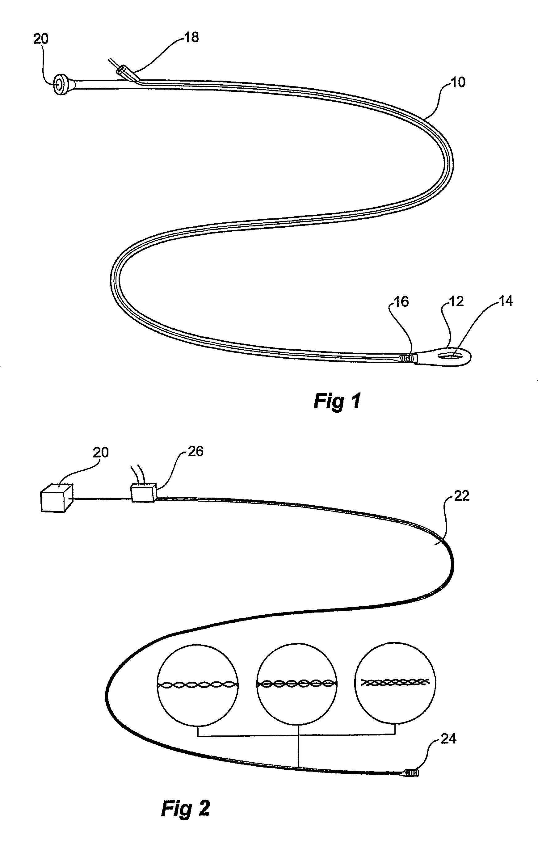
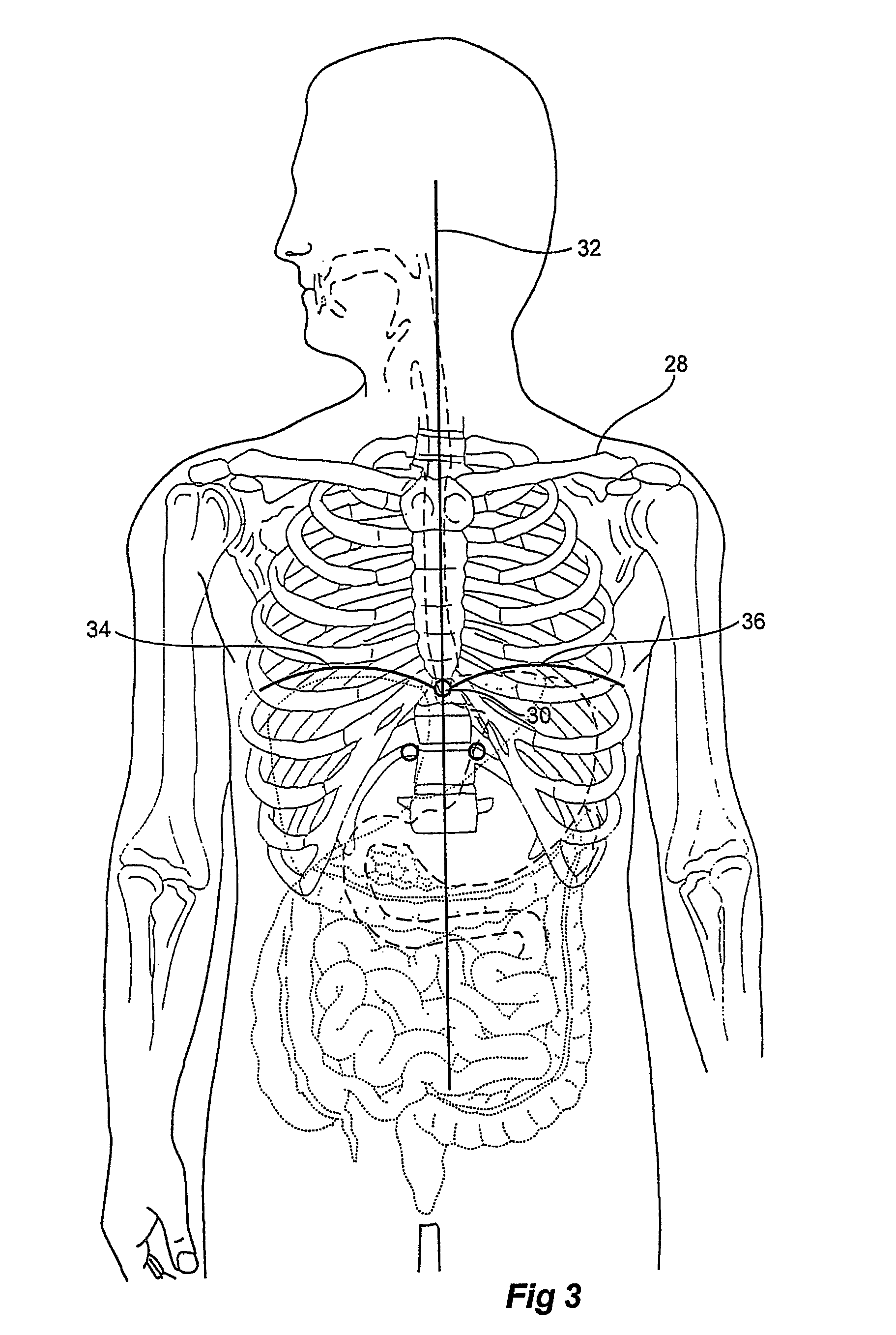
[0072]FIG. 1 depicts a single lumen catheter having located near its caudal / distal end, a coil, which is used to emit a signal that can be detected by an apparatus not unlike that described in U.S. Pat. No. 5,099,845. That patent is in the name of Micronix Pty Ltd and is hereby incorporated into this specification by reference. The incorporation of the above-mentioned patent does not and should not be construed as an admission of the content of the specification having entered the common general knowledge of those skilled in the art.

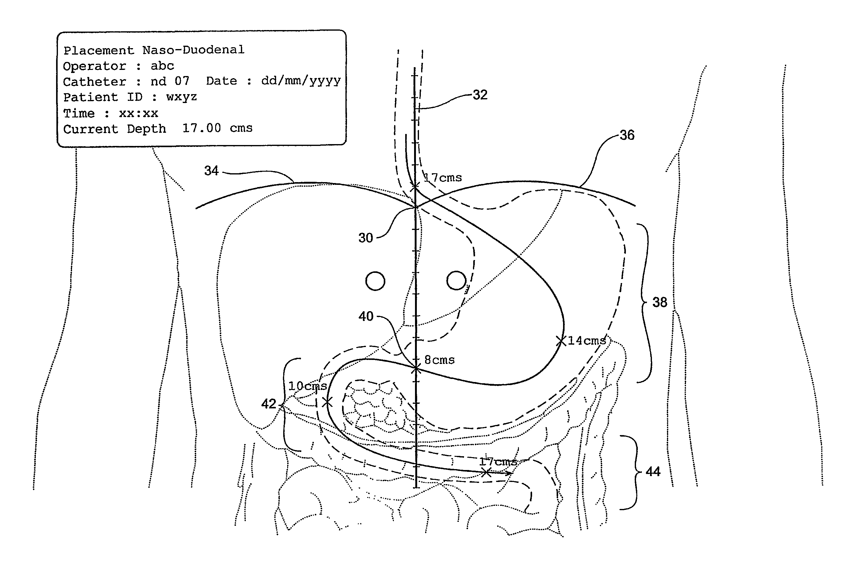
[0073]The apparatus of the invention described in the above-mentioned patent provides a means to determine both the depth and position of a coil located on the end of a catheter as well as its orientation. The type of catheter is of no great importance to the principle and method of the invention.

[0074]The depth and position determining apparatus, also referred to herein as the detector apparatus, is generally of the type disclosed in the above-mentioned...


PUM


Abstract

This invention relates to a method of catheter and radiating coil location in a human body and in particular to the determination over time of the location of the tip of a catheter as it is inserted and during its use in the body. In particular when a radiating coil is used in conjunction with a catheter, a coil locating device can be used to determine the distance the coil is from the device and hence its depth in the body of a patient. To assist a clinician using the coil-locating device, a display is provided that shows both a reference image of a part or portion of a body (non-subject body) and an image of the coil located on the display with reference to the reference image. This is achieved by locating the coil-locating device on or over a predetermined landmark on the patient's body. The coil and its associated signal wires can be incorporated into a stylet, guide wire or a catheter. The coil locating device has a preferable triangular shape in plan view that allows it uppermost apex to be orientated towards the head of the patient and for an axis of the device to be aligned with the mid sagittal plane of the patient. Preferable landmarks on a human body include the xiphoid sternal junction and the caudal / mid sagittal aspect of the jugular sternal notch.

Description

CROSS REFERENCE TO RELATED APPLICATIONS[0001]The present application is a continuation that claims priority to and the benefit of U.S. patent application Ser. No. 10 / 362,273, filed on Feb. 21, 2003, which is a 35 U.S.C. §371 filing based on PCT / AU01 / 01051 filed on Aug. 23, 2001, which claims priority and the benefit of Australian Patent Application No. PR 5250 filed in the Australian Patent Office on May 24, 2001, and Australian Patent Application No. PQ 9592 filed in the Australian Patent Office on Aug. 23, 2000, the entire contents of which are incorporated herein by reference.[0002]This invention relates to a method of catheter and radiating coil location in a human body and in particular to the determination over time of the location of the tip of a catheter as it is inserted and during its use in the body and / or its route through the body.BACKGROUND[0003]For ease of explanation, the guidance and placement and ongoing maintenance of a catheter for enteral nutrition will be descr...

Claims


Application Information

Patent Timeline
Patent Type & Authority Patents(United States)
IPC IPC(8): A61B5/05A61B5/06A61B19/00A61J15/00A61M25/00A61M25/095
CPCA61B5/06A61B5/065A61B5/061A61B5/6851A61B5/6852A61B5/742A61M25/0105A61M25/09A61B19/5244A61B2019/507A61B2019/5251A61B2019/5287A61B2019/5483A61M2025/0166A61B5/743A61J15/0007A61J15/0069A61B2090/3983A61B2090/363A61B34/20A61B2034/107A61B2034/2051A61B5/062A61B90/36
Inventor BESZ, WILLIAM JOHNCHORLEY, DONALD PHILIPBRASTED, STUARTWALKER, ROBERT ANTHONYWALKER, LEGAL REPRESENTATIVE, KATHLEEN MARIA
Owner AVENT INC
Why Eureka
Try Eureka