
Diversity antenna system with electrical tilt

a technology of antenna system and tilt, applied in antennas, polarisation/directional diversity, transmission, etc., can solve the problems of limiting the deployment of new sites, limiting the number of antennas on existing sites, and reducing the visual impact of the environmen

Inactive Publication Date: 2012-09-18
QUINTEL CAYMAN LTD
View PDF29 Cites 11 Cited by
  • Summary
  • Abstract
  • Description
  • Claims
  • Application Information

AI Technical Summary

Benefits of technology

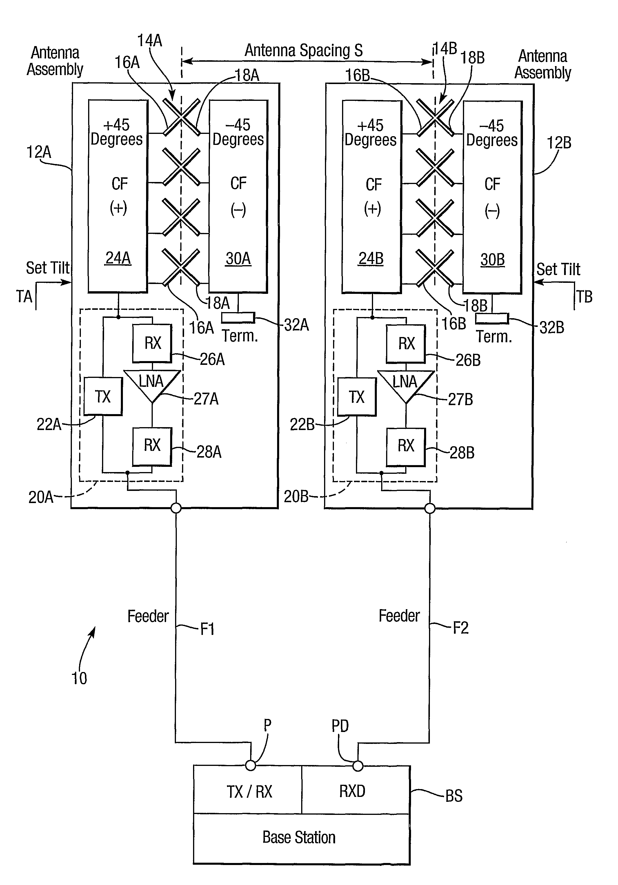
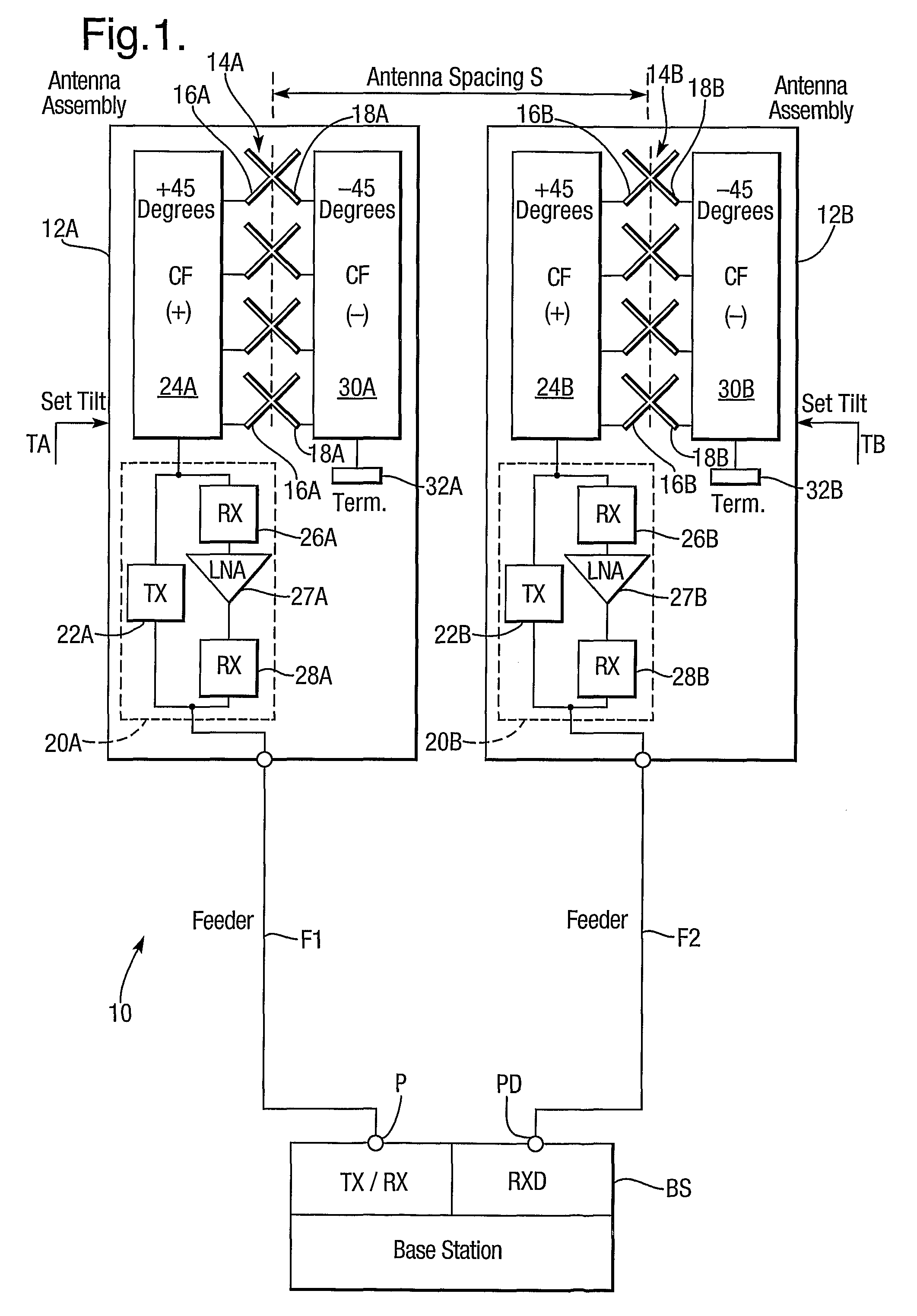
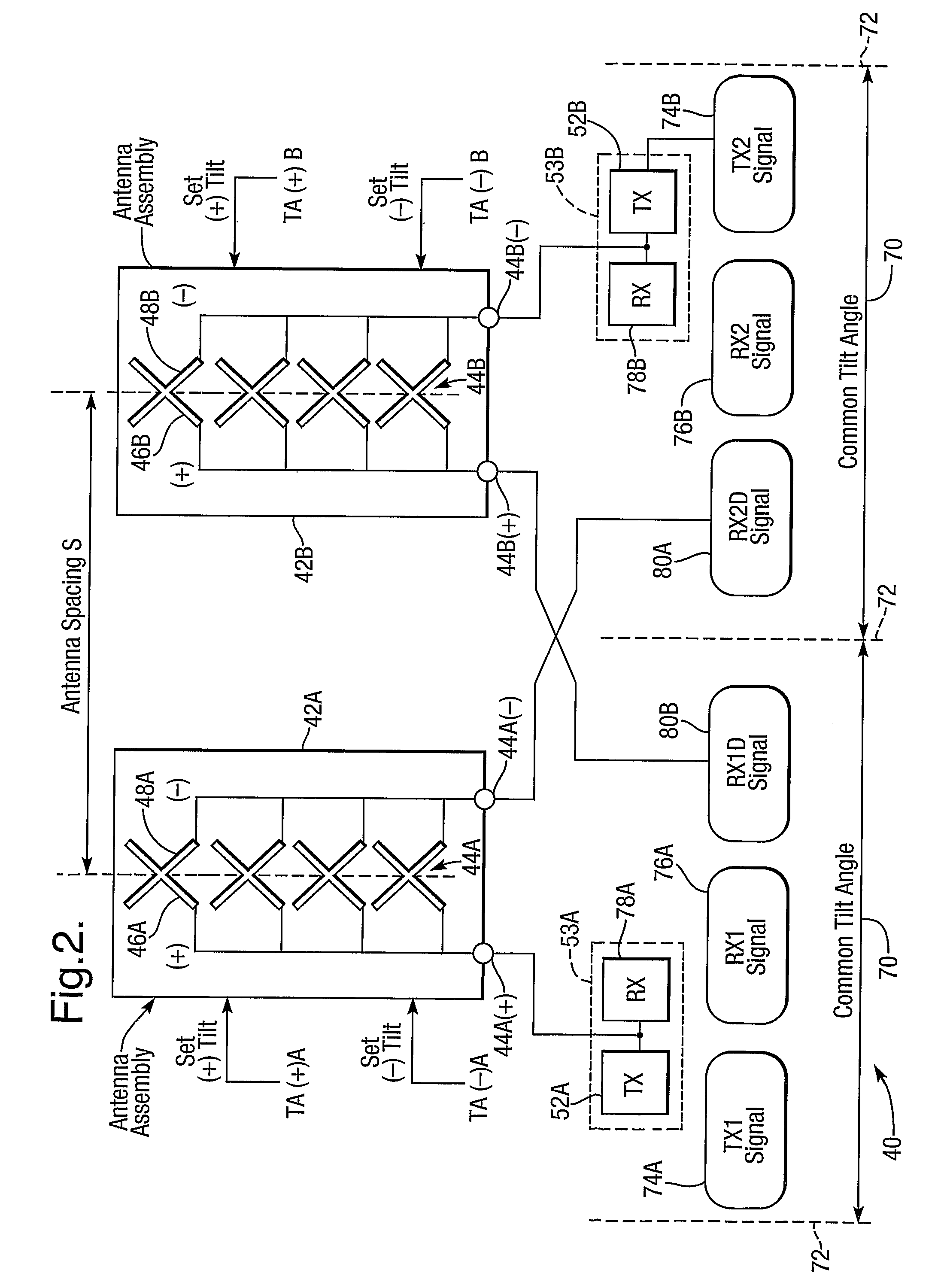
[0014]The invention provides the advantage that it is useable with different carrier frequencies and different independently adjustable angles of electrical tilt: this provides capability for e.g. implementing a different cellular radio standard and / or adding a different operator without the need to provide additional antenna assemblies which would increase visual impact on the environment.
[0026]The method of the invention provides the advantage that it can implement different carrier frequencies and different independently adjustable angles of electrical tilt: this provides capability for e.g. implementing a different cellular radio standard and / or adding a different operator without the need to provide additional antenna assemblies which would increase visual impact on the environment.

Problems solved by technology

Moreover, such replicas become decorrelated with one another.
Operators of cellular radio network face increasing demand for traffic capacity, but are subject to planning or zoning restrictions which limit deployment of new sites or addition of antennas to existing sites.

Method used


Image

  • Diversity antenna system with electrical tilt
  • Diversity antenna system with electrical tilt
  • Diversity antenna system with electrical tilt

Examples


embodiment 140

[0095]The embodiment 140 of the invention described with reference to FIG. 3 has the advantages of the system 40 and in addition the following:[0096](a) the embodiment 140 adds third and fourth transmit signals with different carrier frequencies without requiring to combine signals using filter combiners or 3 dB hybrid combiners;[0097](b) additional transmit signals with different carrier frequencies may be added using filter combiners but without 3 dB hybrid combiners; and[0098](c) the option of transmit space diversity for any of the carrier frequencies is available.

[0099]Further base stations (or carrier frequencies) having contiguous frequencies may be added to the embodiments described with reference to FIGS. 2 and 3 without incurring combining loss in a 3 dB combiner (which is a feature of prior art contiguous frequency combining): this may be implemented using an individual tilt method described in published International Application No. WO 03 / 043127.

[0100]Other embodiments o...

embodiment 240

[0117]Referring now to FIG. 5, there is shown a further antenna system 340 of the invention which is a simplified version of that described with reference to FIG. 4. It is equivalent to the earlier embodiment 240 with the sole exception that the base station filter assembly 250 is replaced by a simplified equivalent comprising a combination of two duplex filters 343A and 343B associated with first and second base stations BS51 and BS52 respectively. It is for use with receive signals having non-contiguous carrier frequencies separable by conventional filters as discussed earlier (its transmit signals need not be non-contiguous). Co-polarisation or anti-polarisation tilt coupling may be implemented as required. Parts equivalent to those described earlier are like referenced—with a prefix 300 replacing 200 where numerically referenced. Description will be directed to aspects of difference between the embodiments 340 and 240.

[0118]The first duplex filter 343A has a narrow band transmit...

embodiment 340

[0120]The embodiment 340 represents a simplification compared to that described with reference to FIG. 4, because it has a reduced number of filters.

[0121]Referring now to FIG. 6, there is shown a further antenna system 440 of the invention with two base stations, i.e. first and second base stations BS61 and BS62, and three feeders F61, F62 and F63; it is suitable for use with contiguous frequencies and co-polarisation or anti-polarisation tilt coupling is available. The antenna system 440 has antenna assemblies 454A and 454B largely as described with reference to FIGS. 3 and 4 for antenna assemblies 254A, 254B, 354A and 354B. The antenna assemblies 454A and 454B of FIG. 6 are equivalent to those of earlier embodiments 240 and 340 with the sole exception that receive signals associated with pairs of corporate feeds 443A, 445A and 443B, 445B in respective antenna stacks 444A and 444B are no longer combined on respective single feeders F61 and F62. Description will be directed to aspe...


PUM


Abstract

A diversity antenna system with electrical tilt has two dual polarized, tilt adjustable antenna stacks (44A) and (44B) with physical separation providing space diversity. Each antenna stack (44A) or (44B) has two polarizations associated with independently adjustable electrical tilt angles. The electrical tilt angles of each antenna stack (44A) or (44B) are controlled to be equal to those of the other antenna stack to provide co-polarization or anti-polarization tilt coupling. The antenna system (40) may operate with multiple carrier frequencies each associated with a respective pair of polarizations of different antenna stacks (44A) and (44B) with co-polarization or anti-polarization tilt coupling. Antenna tilt angles are controllable so that different carrier frequencies are associated with independently adjustable angles of electrical tilt. The system may be used with groups of both contiguous and non-contiguous carrier frequencies.

Description

BACKGROUND OF THE INVENTION[0001](1) Field of the Invention[0002]This invention relates to a diversity antenna system with electrical tilt, i.e. a phased array antenna system with space diversity and electrical tilt capability. It is relevant to many antenna systems such as those used for telecommunications, for example cellular mobile radio networks commonly referred to as mobile telephone networks. Such networks include second generation (2G) mobile telephone networks implemented by a cellular radio standard such as GSM and third generation (3G) mobile telephone networks implemented by a cellular standard such as the Universal Mobile Telephone System (UMTS). Other cellular radio standards include IS95 and WCMA2000.[0003](2) Description of the Art[0004]Operators of conventional cellular radio networks generally employ their own base stations each of which is connected to one or more antennas. In such a network, the antennas are a primary factor in defining the desired coverage area...

Claims


Application Information

Patent Timeline
IPC IPC(8): H01Q3/00H01Q21/06H01Q21/24H04B7/10
CPCH01Q1/246H01Q21/24H04B7/10
Inventor BARKER, DAVID EDWINTHOMAS, LOUIS DAVIDNEWBOLD, STEPHEN THOMASHASKELL, PHILIP EDWARD
Owner QUINTEL CAYMAN LTD
Learn More