
Method for reconstructing a 3D presentation

a 3d reconstruction and hollow organ technology, applied in the field of 3d reconstruction of hollow organs, can solve the problems of extreme radiation load for patients, inability to 3d reconstruct two-dimensional catheter images, and only deliver information about the lumen, and achieve the effect of increasing radiation dos

Active Publication Date: 2012-09-25
SIEMENS HEALTHCARE GMBH
View PDF7 Cites 28 Cited by
  • Summary
  • Abstract
  • Description
  • Claims
  • Application Information

AI Technical Summary

Benefits of technology

This method provides a precise 3D map of the hollow organ's structure, including the wall, without additional devices and reduces patient radiation exposure by determining the most probable withdrawal path and correcting for catheter deviations, resulting in a more accurate representation.

Problems solved by technology

These methods at best however only deliver information about the lumen, not about the wall structure of the vessel.
In such cases mostly two-dimensional sectional images are obtained, with a 3D reconstruction of these two-dimensional catheter images not being possible a priori because of the unknown position and orientation in the hollow organ at the moment when the image is recorded.
The continuous recording of fluoroscopy images leads in this case however to an extreme radiation load for the patient.
The disadvantage of this method is that additional devices and special catheters are needed.
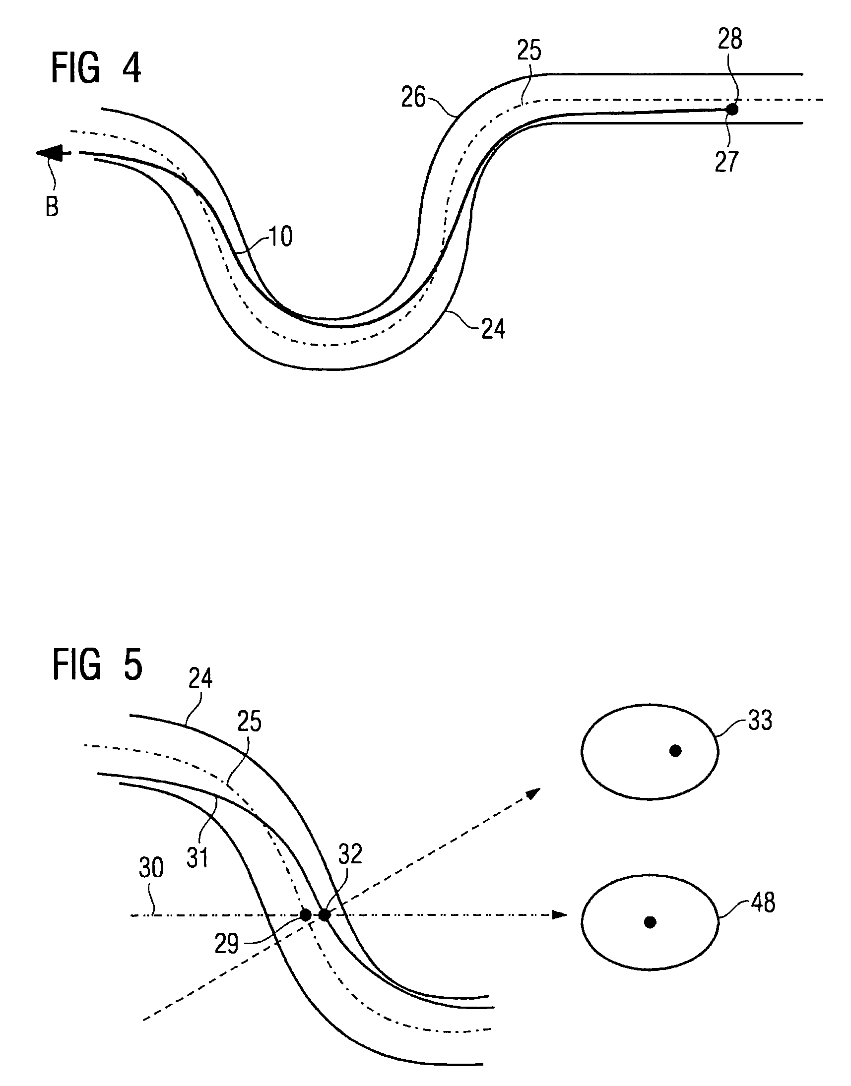
However, two sources of error are then present:a) On the one hand the catheter diameter is usually far smaller than the vessel diameter, i.e. the catheter will generally not be located in the center of the vessel lumen.
This produces different effective withdrawal lengths, and in addition the alignment of the catheter can change during the withdrawal.b) Another problem is that the orientation of the IVUS image plane relative to the vessel is unknown with this method.
This means that distortions can arise for example during the reconstruction.

Method used


Image

  • Method for reconstructing a 3D presentation
  • Method for reconstructing a 3D presentation
  • Method for reconstructing a 3D presentation

Examples


Embodiment Construction

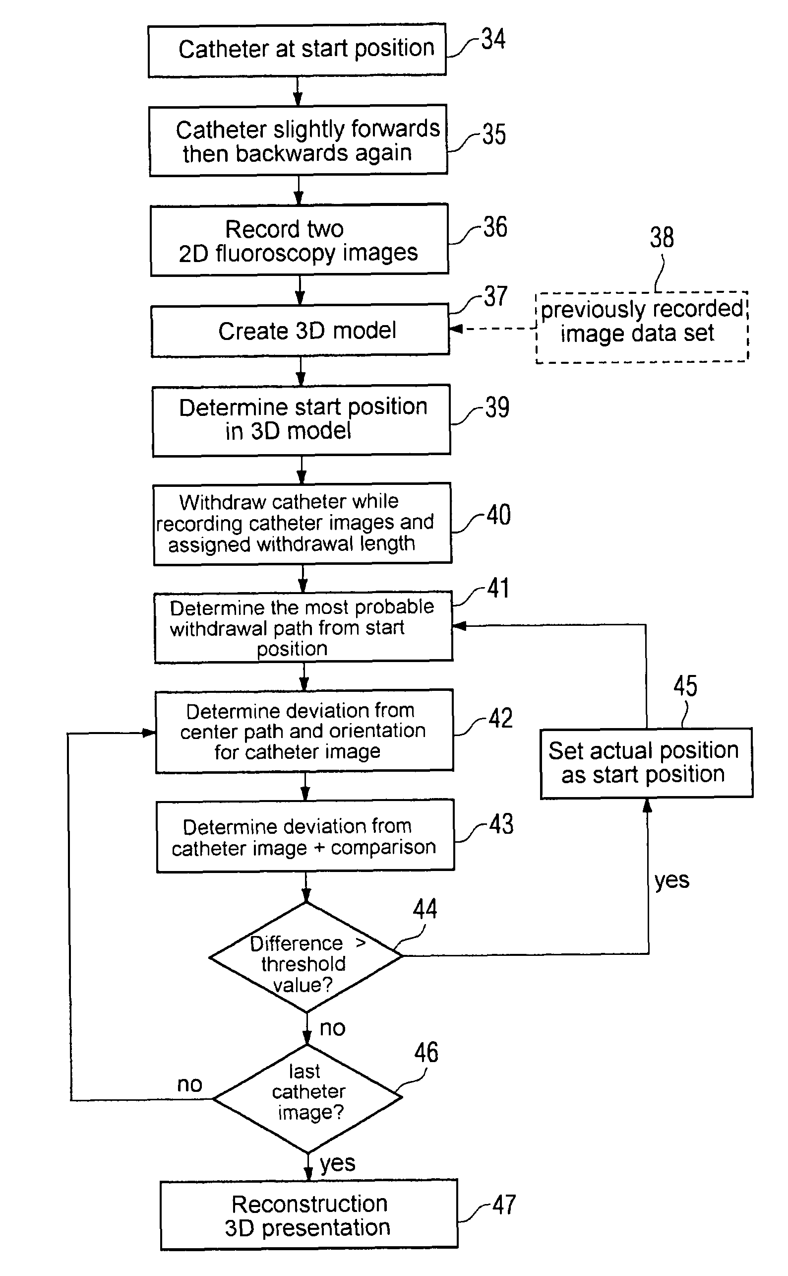
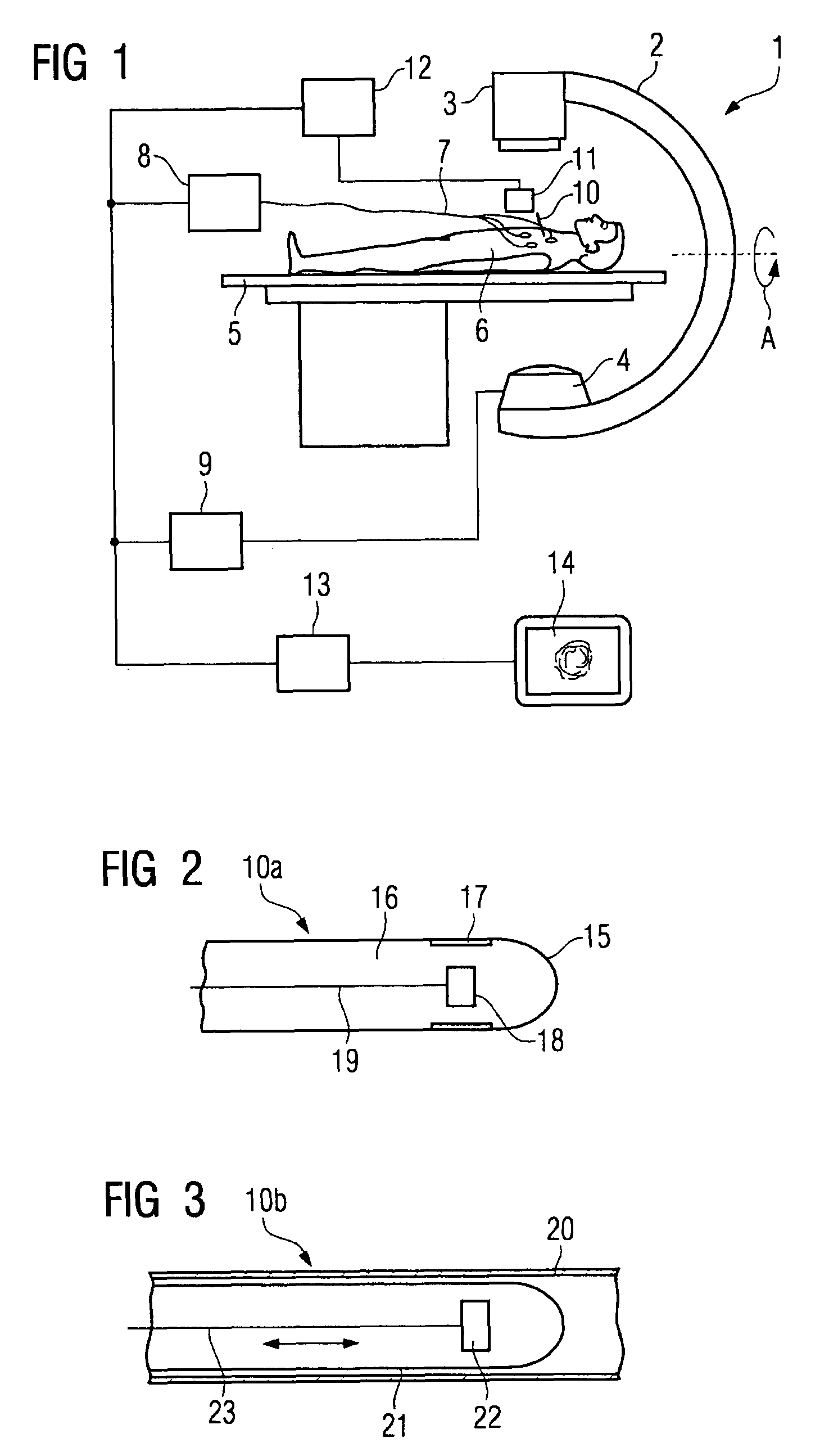
[0047]FIG. 1 shows a medical examination device 1, suitable for executing the inventive method. A C-arm-x-ray system 2, comprising a radiographic source 3 and a radiation detector 4, as indicated by the arrow A, is supported to allow rotation, so that fluoroscopy images can be recorded from different angles. A biplanar x-ray device can also be used as an alternative. A patient 6 is arranged on a bed 5. The ECG value of the patient is measured using suitable recording means 7, processed in an ECG control unit 8 and assigned to an ECG phase. The connection with the x-ray control unit 9 enables two fluoroscopy images at an angle to each other to be recorded using triggering in the same ECG phase with the aid of the x-ray system 2. A catheter 10 with an image recording device arranged at its tip, not shown in any greater detail here, is introduced into a hollow organ of the patient 6. The catheter control unit 11 monitors the catheter 10 and is also embodied to perform an even withdrawa...


PUM


Abstract

The invention relates to a method for reconstructing a 3D presentation of a hollow organ based on two-dimensional catheter images, comprising: detecting at least two fluoroscopy images at two different angles of the hollow organ; determining a start position of the catheter from the fluoroscopy images in a three-dimensional model of the hollow organ or a catheter guide; determining a probable withdrawal path of the catheter based on the three-dimensional model; withdrawing the catheter while recording the catheter images and assigning a withdrawal length to each catheter image; determining the deviation of the position of the catheter from a central path running through the middle of the hollow organ and the orientation of the catheter for each catheter image based on the withdrawal path and the withdrawal length; and reconstructing the 3D presentation from the two-dimensional catheter images as well as the deviation of the position of the catheter.

Description

CROSS REFERENCE TO RELATED APPLICATIONS[0001]This application claims priority of German application No. 10 2006 011 242.3 filed Mar. 10, 2006, which is incorporated by reference herein in its entiretyFIELD OF THE INVENTION[0002]The invention relates to a method for reconstructing a 3D presentation of a hollow organ on the basis of two-dimensional catheter images recorded during its withdrawal by a catheter comprising an image recording device.BACKGROUND OF THE INVENTION[0003]For diagnosis and therapy planning in medical fields relating to hollow organs, especially in interventional cardiology, the process of obtaining information about the hollow organ from x-ray based imaging methods is known. These methods at best however only deliver information about the lumen, not about the wall structure of the vessel. Invasively applied imaging catheters, which include an imaging device, provide information about the wall structure. These imaging devices are based for example on ultrasound im...

Claims


Application Information

Patent Timeline
Patent Type & Authority Patents(United States)
IPC IPC(8): A61B5/05
CPCA61B6/12A61B6/466A61B6/504A61B6/541G06T19/00A61B5/0066A61B5/0084A61B6/4441A61B8/12
Inventor CAMUS, ESTELLEREDEL, THOMAS
Owner SIEMENS HEALTHCARE GMBH
Learn More