Vehicle lighting device

a technology for lighting devices and vehicles, applied in the direction of lighting support devices, fixed installations, lighting and heating apparatus, etc., to achieve the effects of improving appearance or design properties, improving heat transmission, and reducing dimensions in longitudinal and transverse directions

Inactive Publication Date: 2012-10-02
ICHIKOH IND LTD
View PDF6 Cites 6 Cited by
  • Summary
  • Abstract
  • Description
  • Claims
  • Application Information

AI Technical Summary

Benefits of technology

[0055]The vehicle lighting device according to the first aspect of the present invention allows components made up of a heat sink member, a semiconductor-type light source, a power-feeding holder, and a fixing member to be assembled in one top-to-down direction by means for solving the above-described problems. In other words, the semiconductor-type light source is directly placed on a top face of the heat sink member from above; the power-feeding holder is set on the semiconductor-type light source and the heat sink member from above; the semiconductor-type light source is held at the heat sink member side, enabling power feeding to the semiconductor-type light source; the fixing member is adapted to cover the power-feeding holder from above, fixing the power-feeding holder to the heat sink member and sandwiching and fixing the semiconductor-type light source between the power-feeding holder and the heat-sink member. In this manner, the vehicle lighting device according to the first aspect of the present invention allows components made up of the heat sink member, the semiconductor-type light source, the power-feeding holder, and the fixing member to be assembled in one top-to-down direction, thus improving workability of assembling components and enabling automated assembling of components.
[0061]Furthermore, in the vehicle lighting device according to the fourth aspect of the present invention, a heat sink member and a semiconductor-type light source can be positioned by means of a positioning portion, a spring portion, and a receptacle portion of the heat sink member. In addition, the heat sink member and the power-feeding holder can be positioned by means of the positioning portion of the heat sink member and the semiconductor-type light source. Further, the semiconductor-type light source and the power-feeding holder can be positioned via the heat sink member. As a result, in the vehicle lighting device according to the fourth aspect of the present invention, the heat sink member, the semiconductor-type light source, and the power-feeding holder can be mutually positioned with high precision. Moreover, the heat sink member, the semiconductor-type light source, and the power-feeding holder that were positioned with high precision are fixed by means of the fixing member, so that the light from the semiconductor-type light source can be controlled with high precision and light distribution can be controlled with high precision.

Problems solved by technology

Therefore, the conventional vehicle lighting device entails problems concerning assembling between the assembly case and the diode of the light emitting element; and assembling among the light emitting element, the unit mounting portion, and the plate-shaped spring member, i.e., workability of assembling components.

Method used


Image

  • Vehicle lighting device
  • Vehicle lighting device
  • Vehicle lighting device

Examples


embodiment (

Embodiment(s)

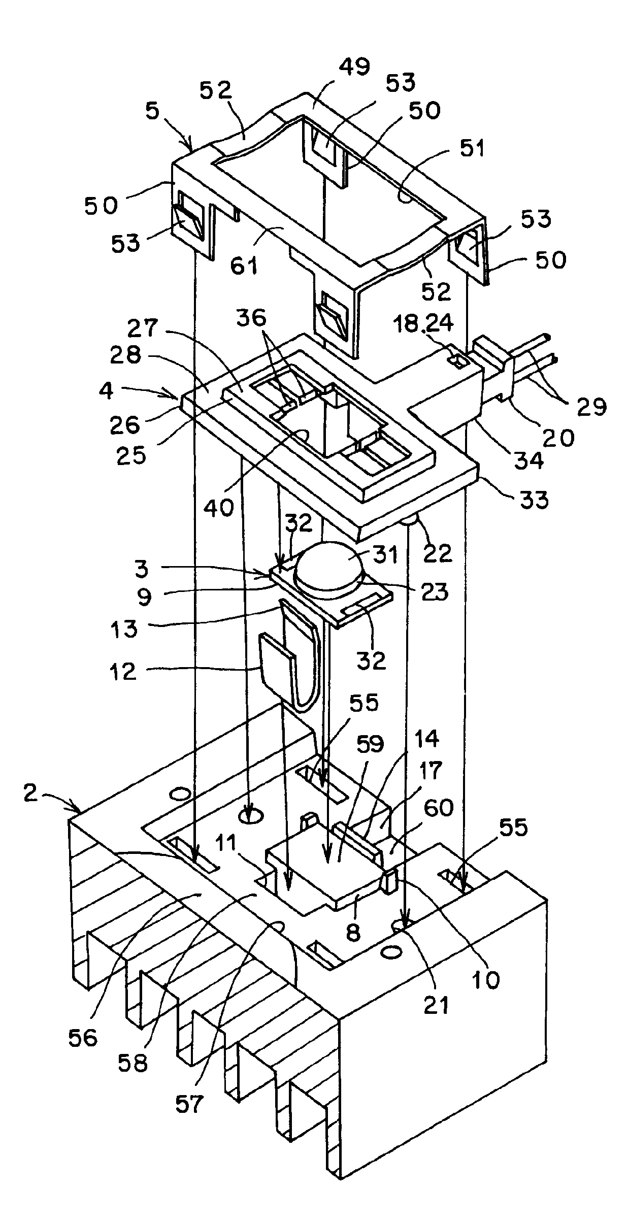
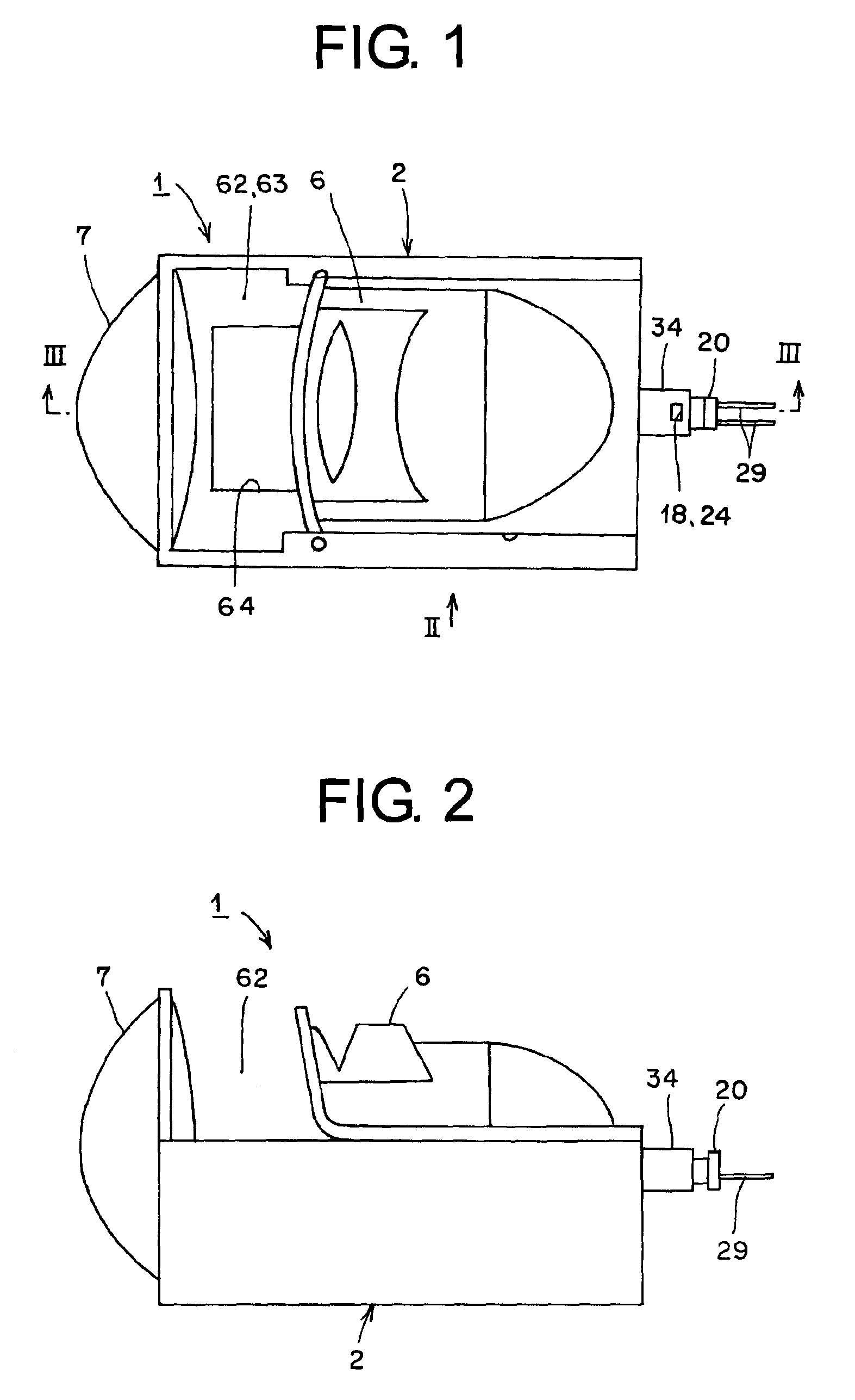
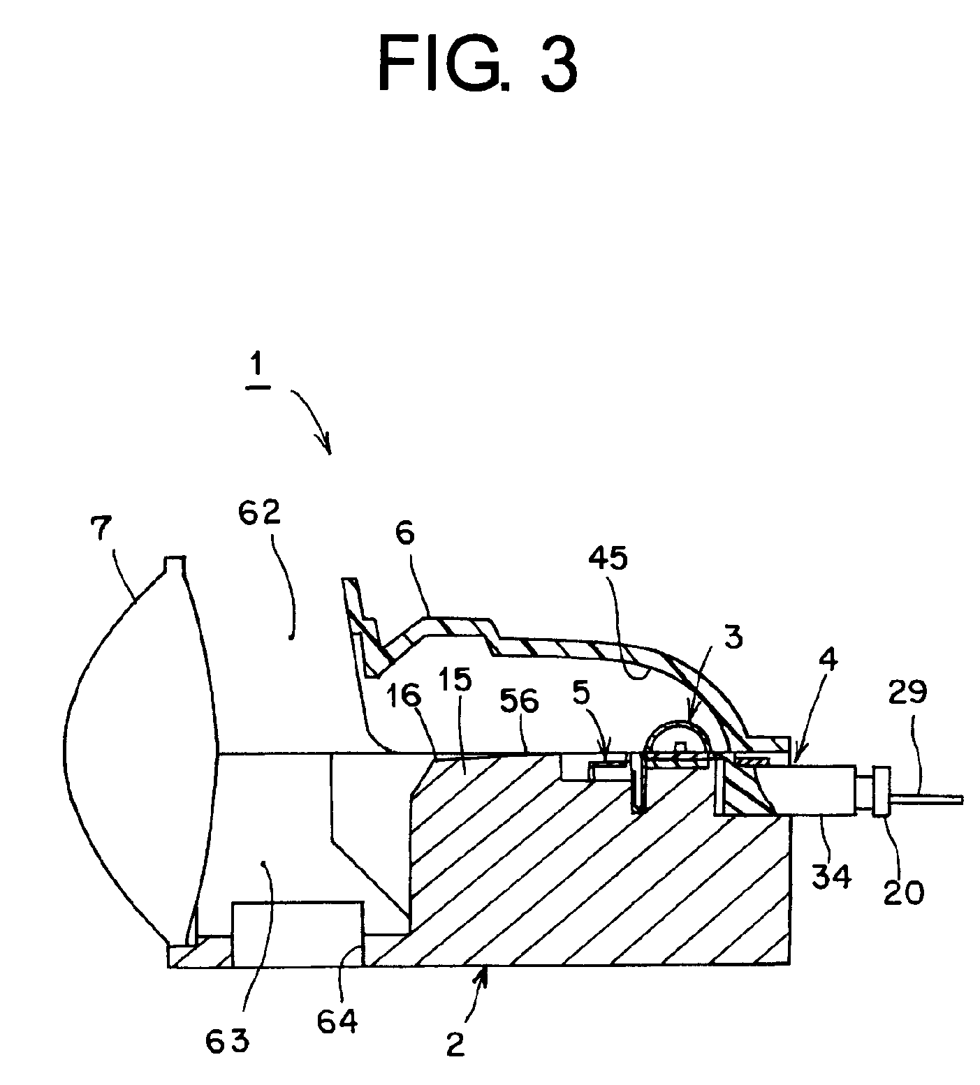
[0083]Hereinafter, a constitution of a vehicle lighting device in this embodiment will be described. In the figures, reference numeral 1 denotes a vehicle lighting device in this embodiment. The vehicle lighting device 1 is a headlamp for automobile, for example, and forms a projector-type unit structure. The vehicle lighting device 1, as shown in FIGS. 1 to 3, is made up of: a heat sink member 2; a semiconductor-type light source 3; a power-feeding holder 4; a fixing member 5; a reflector 6; a projecting lens 7; and a lamp housing and a lamp lens of headlamp for automobile, although not shown (such as a transparent outer lens, for example).

[0084]The heat sink member 2, the semiconductor-type light source 3, the power-feeding holder 4, the fixing member 5, the reflector 6, and the projecting lens 7 constitute a lamp unit. One or more of the lamp units are disposed in a lamp room partitioned by the lamp housing and the lamp lens of the headlamp for automobile, for exampl...


PUM


Abstract

A vehicle lighting device includes: a heat sink member; a semiconductor-type light source directly placed on a top face of the heat sink member; a power-feeding holder which is set on the semiconductor-type light source and the heat sink member, for holding the semiconductor-type light source at the side of the heat sink member and feeding a power current to the semiconductor-type light source; and a fixing member which is covered on the power-feeding holder and fixed to the heat sink member, for fixing the power-feeding holder to the heat sink member and sandwiching and fixing the semiconductor-type light source between the power-feeding holder and the heat sink member. As a result, this vehicle light device improves workability of assembling components.

Description

CROSS-REFERENCE TO RELATED APPLICATIONS[0001]This application claims priority of Japanese Patent Application No. 2008-238234 filed on Sep. 17, 2008. The contents of this application are incorporated herein by reference in their entirety.BACKGROUND OF THE INVENTION[0002]1. Field of the Invention[0003]The present invention relates to a vehicle lighting device using a semiconductor-type light source such as an LED as a light source.[0004]2. Description of the Related Art[0005]A vehicle lighting device of this type has been conventionally known (Japanese Laid-open Patent Application No. 2007-48695, for example). Hereinafter, the above vehicle lighting device will be described. The conventional vehicle lighting device is provided with: a bracket made of a vertical panel, which has an opening, and a unit mounting portion; a light emitting element as an LED assembly for housing a diode in a synthetic resin-based assembly case; and a plate-shaped spring member for fixing and holding the lig...

Claims


Application Information

Patent Timeline
Patent Type & Authority Patents(United States)
IPC IPC(8): B60Q1/00
CPCF21S48/1104F21S48/1109F21S48/1159F21S48/1163F21S48/211F21V29/763F21S48/215F21S48/212F21S48/328F21V29/004F21Y2101/02F21Y2115/10F21S41/148F21S41/155F21S41/19F21S41/192F21S43/14F21S43/19F21S43/195F21S45/47
Inventor TOKUNAGA, HIROTO
Owner ICHIKOH IND LTD
Why Eureka
Try Eureka