Method and configuration for optically detecting an illuminated specimen

a specimen and optical detection technology, applied in the field oflinescanning microscopes, can solve the problems of deficient in providing a simplified configuration for the use of structured illumination in the prior art, and achieve the effect of increasing resolution

Inactive Publication Date: 2012-10-02
CARL ZEISS MICROSCOPY GMBH
View PDF12 Cites 4 Cited by
  • Summary
  • Abstract
  • Description
  • Claims
  • Application Information

AI Technical Summary

Problems solved by technology

However, the prior art has been deficient in providing a simplified configuration for the use of structured illumination, particularly in a line scanning application.

Method used


Image

  • Method and configuration for optically detecting an illuminated specimen
  • Method and configuration for optically detecting an illuminated specimen
  • Method and configuration for optically detecting an illuminated specimen

Examples


Embodiment Construction

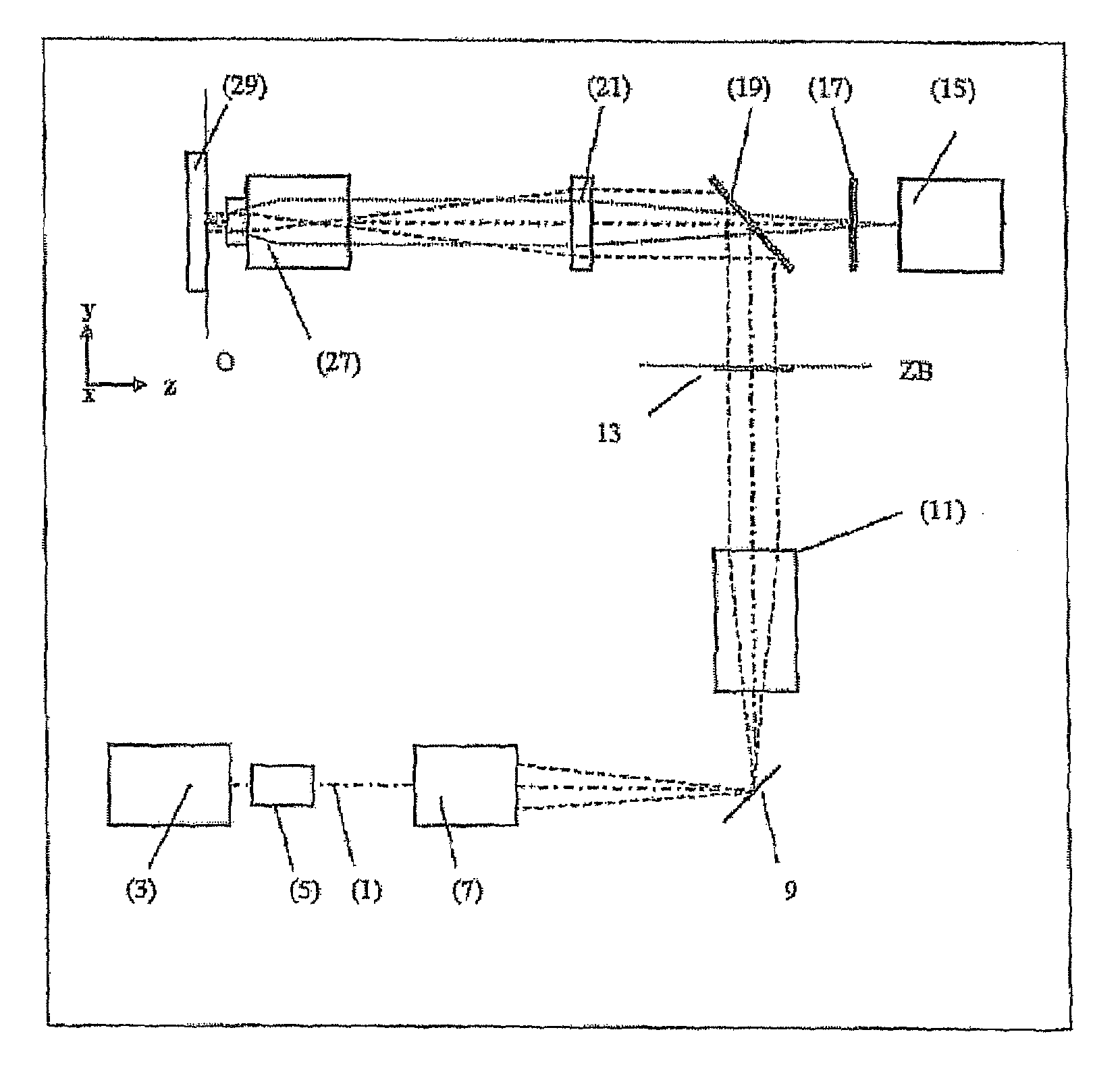
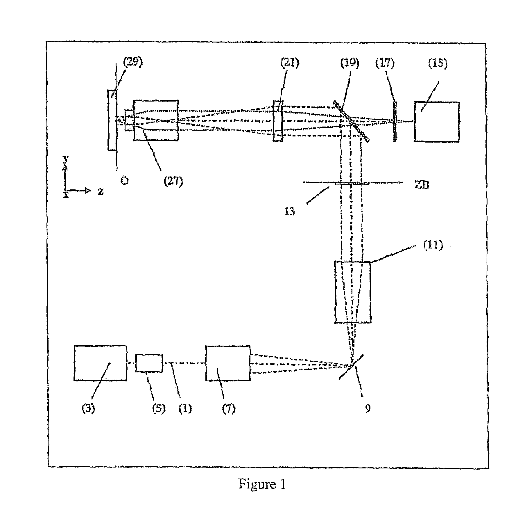
[0015]FIG. 1 schematically shows the assembly of an embodiment of a microscope according to the present invention which includes: an optical axis (1), a light source (3), a switchable attenuator / AOM (i.e., accusto-optical modulator) (5), a line shaping optical system (7), a scanner (9) with a rotational axis perpendicular to the drawing plane (9), a scanning optics system (11), mask (13) with a periodic structure in the intermediate image plane conjugate to the specimen with means for a translation perpendicular to the drawing plane and the rotation about the optical axis, a spatially resolved area sensor (15), e.g., a CCD, an emission filter (17), a main dichroic beam splitter (19), a barrel lens (21), a microscope objective lens (27), and specimen (29).

[0016]Located in the detection beam path in the direction of the light that is coming from the specimen (29) are an objective lens (27) that is corrected for an infinity beam path, a barrel lens (21), a main dichroic beam splitter (...


PUM


Abstract

A configuration for the optical detection of a specimen, wherein the specimen or at least part of the specimen is scanned by means of linear illumination by scanning means, means for linear beam shaping of the illuminating light are provided, and the illuminating light has a preferably periodic structure in at least one spatial direction in that means for generating the structure are disposed in the illuminating beam path, light coming from the specimen is detected and images of the specimen are generated therefrom, at least one optical sectional image through the specimen and / or one image with increased resolution is / are calculated from the images, and means for generating the structure are disposed downstream of the scanning means in the direction of the illumination.

Description

CROSS REFERENCE[0001]This application claims the benefit of U.S. provisional patent application 60 / 990,018 filed on Nov. 26, 2007, the contents of which are hereby incorporated by reference herein.FIELD OF THE INVENTION[0002]The present invention relates to a line-scanning microscope with spatially resolved detection of the entire image field.BACKGROUND OF THE INVENTION[0003]It has been an objective of those within the field of the invention to enhance resolution and contrast. The use of structure illumination to achieve such objectives has been an area of investigation and development. However, the prior art has been deficient in providing a simplified configuration for the use of structured illumination, particularly in a line scanning application. Compared to the prior art, the proposed configuration has been simplified and can offer advantages in the field.SUMMARY OF THE INVENTION[0004]In accordance with the invention, a configuration, such as may be found in a scanning microsco...

Claims


Application Information

Patent Timeline
Patent Type & Authority Patents(United States)
IPC IPC(8): G06K9/00G01J1/42G02B21/00
CPCG02B21/0032G02B21/0048G02B21/0056
Inventor KEMPE, MICHAELWOLLESCHENSKY, RALF
Owner CARL ZEISS MICROSCOPY GMBH
Why Eureka
Try Eureka