
Analyte sensor method and apparatus

Inactive Publication Date: 2012-10-02
VOLCANO CORP
View PDF11 Cites 54 Cited by
  • Summary
  • Abstract
  • Description
  • Claims
  • Application Information

AI Technical Summary

Benefits of technology

The patent describes a system for making a sensor that can detect a certain substance in a sample. The system includes a method for making the sensor and a composition that can be used to make the sensor. The sensor can be used to detect the substance in a sample and provide a signal that can be measured. The technical effect of this patent is to provide a way to make a sensor that can detect a specific substance and produce a measurable signal.

Problems solved by technology

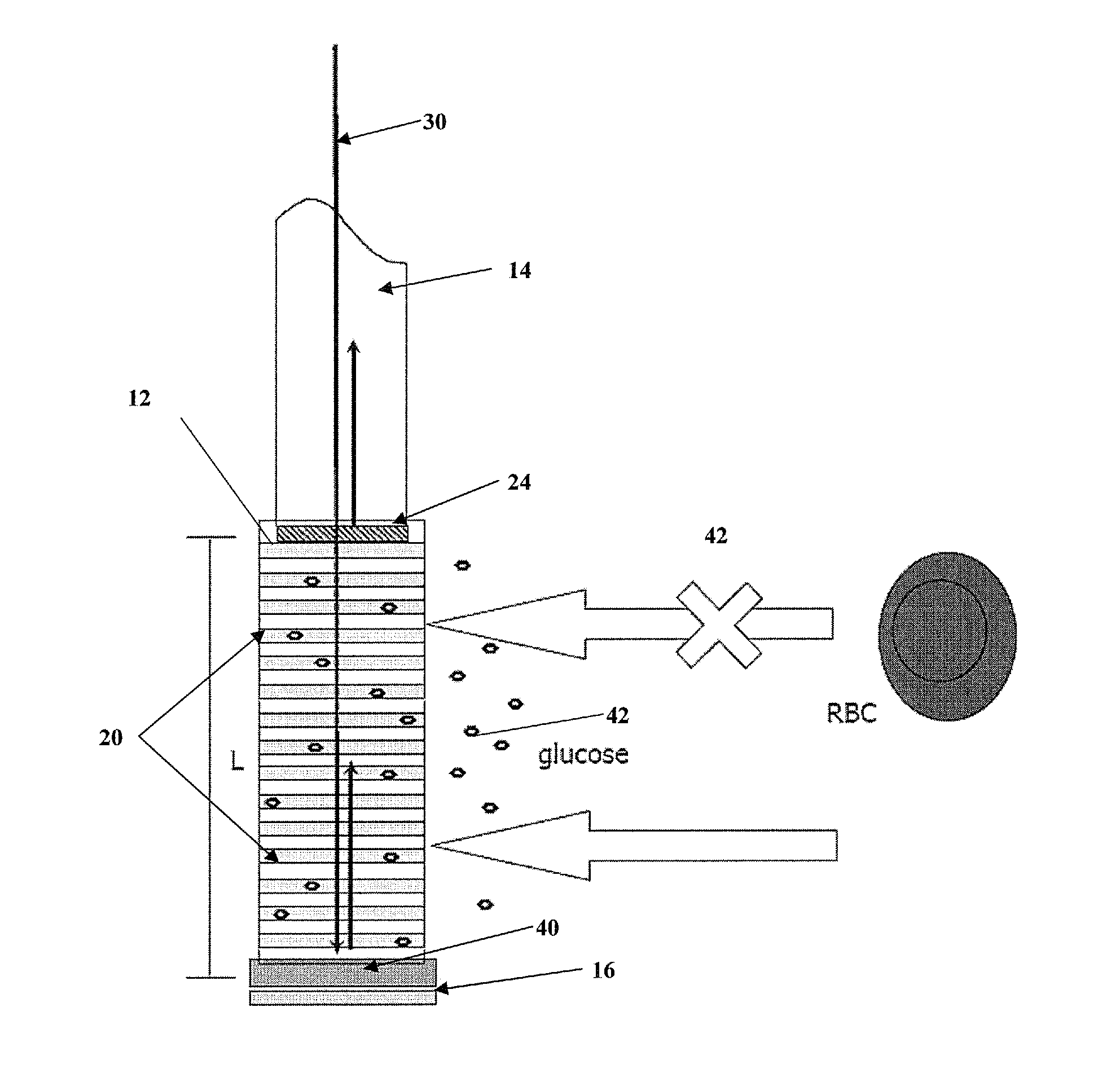
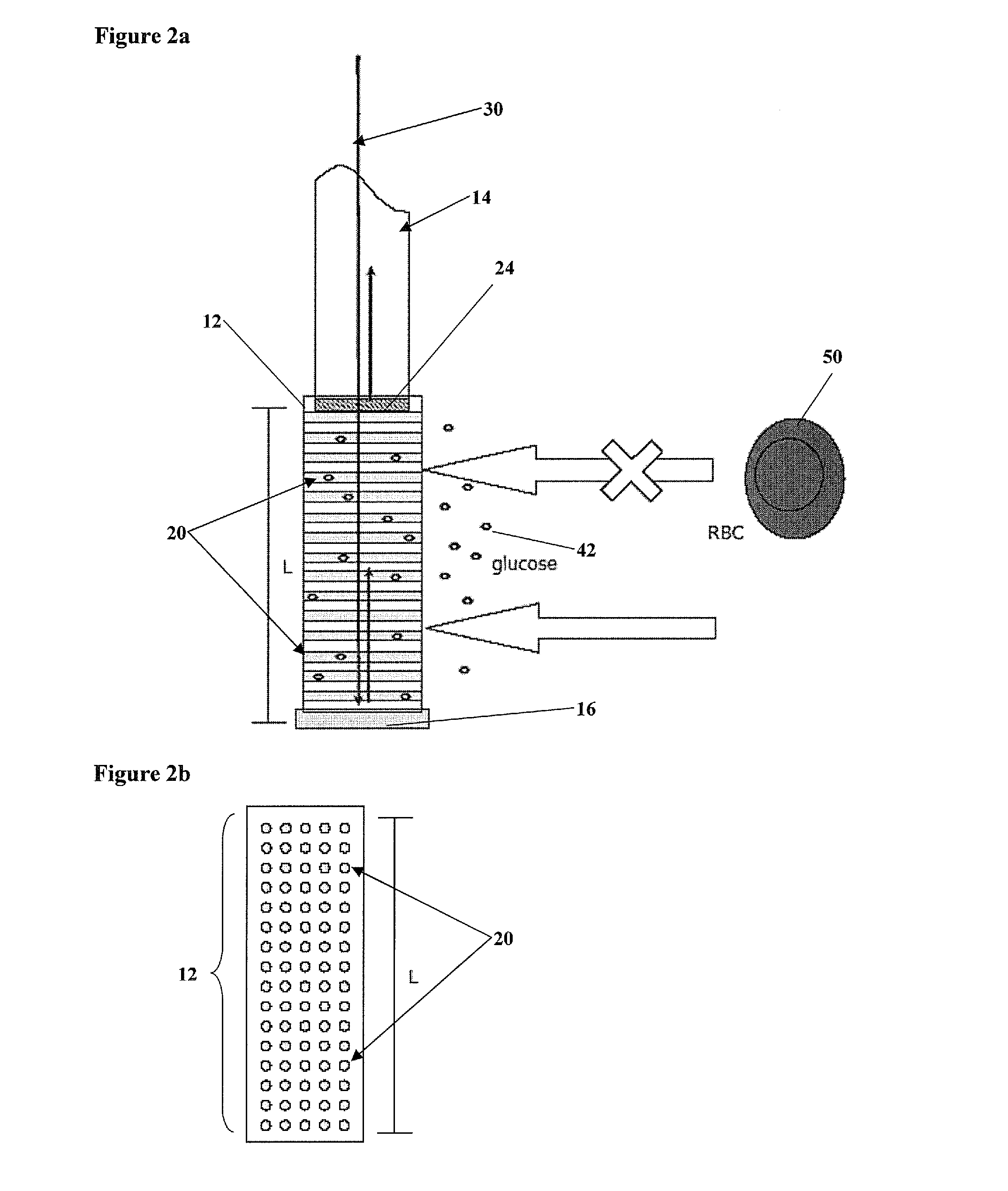
Specific problems arise when optically measuring analytes internally within a vessel, such as backscattering of light due to particulates, cells, and the like.

Method used


Image

  • Analyte sensor method and apparatus
  • Analyte sensor method and apparatus
  • Analyte sensor method and apparatus

Examples


example 1

Quantitative Determination of Glucose Concentration by Swept-Source Spectral Interferometry and Spectral Phase Analysis

[0049]To quantitatively measure glucose concentration in an aqueous solution this example estimates the optical path length change of the solutions by utilizing a swept-source spectral interferometry and a unique spectral phase analysis. Concentrations of the glucose solutions are in the range of 0-50 mM.

[0050]The swept-source spectral interferometer system 100 is depicted in FIG. 8. The swept source spectral interferometer system 100 is a fiber-based common-path spectral interferometer and includes a light source 110, an interferometer, and a detector. The light source 110 is a high-resolution, broad-band frequency swept laser source (Precision Photonics, TLSA1000); wavelength range 1520-1620 nm, and maximum output power 0.4 mW. The spectral line width of the swept laser is specified at 150 KHz. The interferometer is a Michelson-type common-path interferometer and ...


PUM


Abstract

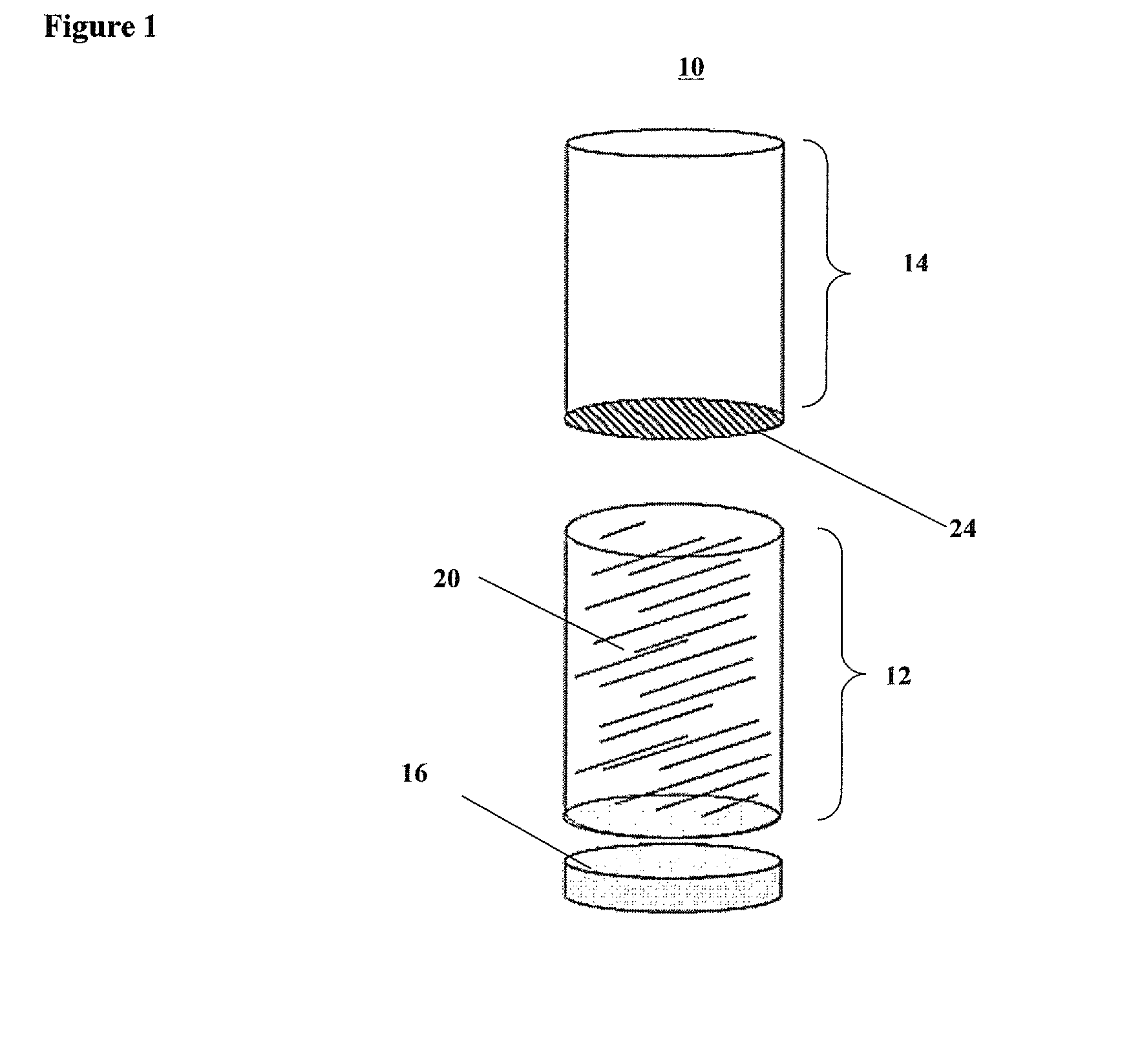
The invention generally relates to systems, methods, and apparatuses for an analyte sensor. In one aspect, an analyte sensing device comprises a sensor body member including at least one nanopore and an optical conduit in optical communication with the sensor body member. The optical conduit transmits optical energy to the sensor body member and receives reflected optical energy back from the sensor body member. A photodetector is optically coupled to the optical conduit to determine an optical parameter from the reflected optical energy.

Description

CROSS-REFERENCE TO RELATED APPLICATIONS[0001]The present application claims the benefit of U.S. Provisional Application Ser. No. 60 / 864,280, filed Nov. 3, 2006. The aforementioned application is herein incorporated by reference in its entirety.BACKGROUND OF THE INVENTION[0002]The present invention relates generally to analyte sensors. More specifically, the invention relates to analyte sensors using Optical Coherence Tomography (OCT).[0003]In OCT, light from a broad band light source is split by an optical fiber splitter with one fiber directing light to a sample path and the other optical fiber directing light to a reference path mirror. The distal end of the sample path can be interfaced with a scanning device, or the like. The reflected light from the scanning device is recombined with the signal from the reference mirror forming interference fringes (measured by a photovoltaic detector) allowing precise depth-resolved imaging or optical measurements to be taken. OCT has the pote...

Claims


Application Information

Patent Timeline
Patent Type & Authority Patents(United States)
IPC IPC(8): A61B5/1455
CPCA61B5/0066A61B5/14532G01N21/4795A61B5/1459A61B2562/0285A61B2562/12
Inventor MILNER, THOMAS E.KEMP, NATHANIEL J.CASTELLA, PAUL
Owner VOLCANO CORP
Learn More