Method and system for replacing a plasma lamp from a resonator assembly

a resonator assembly and plasma lamp technology, applied in the field of lighting techniques, can solve the problems of high initial cost, high energy consumption of edison bulbs, and many limitations of electrode-less lamps, and achieve the effects of improving heat transfer characteristics, improving manufacturability and design flexibility, and facilitating repair and maintenan

Active Publication Date: 2012-10-09
TOPANGA USA
View PDF31 Cites 9 Cited by
  • Summary
  • Abstract
  • Description
  • Claims
  • Application Information

AI Technical Summary

Benefits of technology

[0011]Benefits are achieved over pre-existing techniques using the present invention. In a preferred embodiment, the present apparatus and method includes a replaceable gas filled vessel, including a support body, for easy repair and maintenance. In a specific embodiment, the present invention provides a method and device having configurations of input, output, and feedback coupling elements that provide for electromagnetic coupling to the bulb whose power transfer and frequency resonance characteristics that are largely independent of the conventional dielectric resonator, but can also be dependent upon conventional designs. In a preferred embodiment, the present invention provides a method and configurations with an arrangement that provides for improved manufacturability as well as design flexibility. Other embodiments may include integrated assemblies of the output coupling element and bulb that function in a complementary manner with the present coupling element configurations and related methods for street lighting applications. Still further, the present method and device provide for improved heat transfer characteristics, as well as further simplifying manufacturing and / or retrofitting of existing and new street lighting, such as lamps, and the like. In a specific embodiment, the present method and resulting structure are relatively simple and cost effective to manufacture for commercial applications. Depending upon the embodiment, one or more of these benefits may be achieved. These and other benefits may be described throughout the present specification and more particularly below.

Problems solved by technology

Although highly successful, the Edison bulb consumed much energy and was generally inefficient.
Fluorescent lighting is much more efficient than incandescent lighting, but often has a higher initial cost.
Although somewhat successful, the electrode-less lamp still had many limitations.
As an example, electrode-less lamps have not been successfully deployed.
Additionally, electrode-less lamps are generally difficult to disassemble and assembly leading to inefficient use of such lamps.

Method used


Image

  • Method and system for replacing a plasma lamp from a resonator assembly
  • Method and system for replacing a plasma lamp from a resonator assembly
  • Method and system for replacing a plasma lamp from a resonator assembly

Examples


Embodiment Construction

[0022]According to the present invention, techniques for lighting are provided. In particular, the present invention provides a method and device using a plasma lighting device having one of a plurality of base configurations. Merely by way of example, such plasma lamps can be applied to applications such as stadiums, security, parking lots, military and defense, streets, large and small buildings, vehicle headlamps, aircraft landing, bridges, warehouses, uv water treatment, agriculture, architectural lighting, stage lighting, medical illumination, microscopes, projectors and displays, any combination of these, and the like.

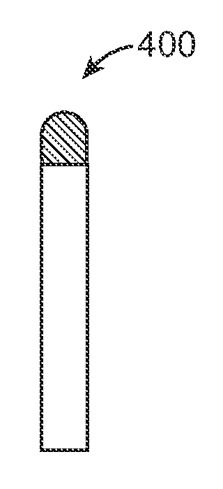
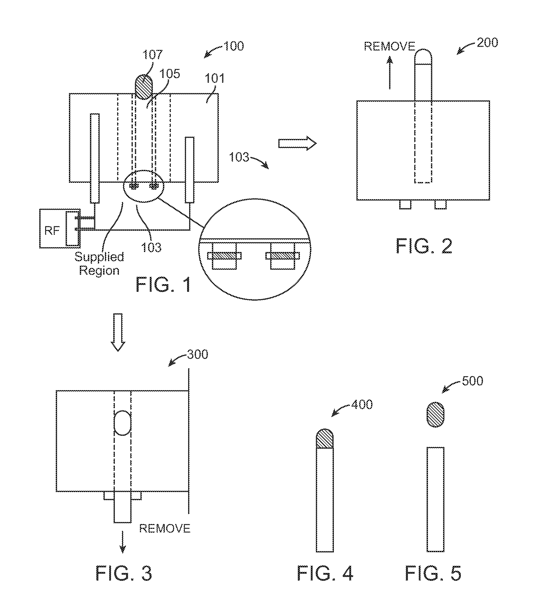
[0023]FIG. 1 is a simplified diagram of a plasma lamp device 100 according to an embodiment of the present invention. This diagram is merely an example, which should not unduly limit the scope of the claims herein. One of ordinary skill in the art would recognize other variations, modifications, and alternatives. As shown, the plasma lamp device has a housing 101...


PUM

PropertyMeasurementUnit
frequencyaaaaaaaaaa
frequencyaaaaaaaaaa
frequencyaaaaaaaaaa

Abstract

A plasma lamp. The lamp includes a housing having a spatial volume defined within the housing. In a specific embodiment, the spatial volume has an inner region and an outer region. The lamp also has a support region coupled to the inner region of the spatial volume and a support body having an outer surface region slidably inserted and disposed within or partially disposed the support region. In a preferred embodiment, the support body has a support length, a support first end, and a support second end. The plasma lamp has a gas-filled vessel coupled to the support first end of the support body. In a preferred embodiment, the gas filled vessel has a transparent or translucent body, an inner surface and an outer surface, a cavity formed within the inner surface. In a preferred embodiment, the cavity is sealed and includes a fill material, which is capable of discharge. The lamp has an rf source operably coupled to at least the first end of the gas-filled vessel. In a specific embodiment, the rf source is configured to cause a discharge of one or more gases in the gas filled vessel.

Description

CROSS-REFERENCES TO RELATED APPLICATIONS[0001]This application claims priority to U.S. Provisional Application No. 61 / 158,701, filed on Mar. 9, 2009, commonly assigned, and incorporated by reference herein for all purpose. This application is also related to U.S. patent application Ser. No. 12 / 484,933, filed on Jun. 15, 2009 and PCT Application Serial No. PCT / US2009 / 048171, filed on Jun. 22, 2009, commonly assigned, and incorporated by reference herein for all purpose.BACKGROUND OF THE INVENTION[0002]The present invention relates generally to lighting techniques. In particular, the present invention provides a method and device using a plasma lighting device having one of a plurality of base configurations. More particularly, the present invention provides a method and resulting system for removing and preferably replacing a plasma bulb for a lighting device, which can be used for a variety of applications. Merely by way of example, such plasma lamps can be applied to applications s...

Claims


Application Information

Patent Timeline
Patent Type & Authority Patents(United States)
IPC IPC(8): H01J9/50
CPCH01J65/044Y10T29/4973
Inventor ESPIAU, FREDERICK M.
Owner TOPANGA USA
Why Eureka
Try Eureka