Substrate processing apparatus and substrate stage used therein

a technology of substrate processing and processing apparatus, which is applied in lighting and heating apparatus, muffler furnaces, etc., can solve the problems of affecting the heat resistance of components disposed at the bottom with a lower level, affecting the effect of heat resistance, and complicating the structure, so as to prevent unnecessary heat application to the bottom area of the processing chamber, enhance the effect, and prevent the effect of heat application

Inactive Publication Date: 2012-10-09
TOKYO ELECTRON LTD
View PDF12 Cites 2 Cited by
  • Summary
  • Abstract
  • Description
  • Claims
  • Application Information

AI Technical Summary

Benefits of technology

[0012]Accordingly, an object of the present invention having been completed by addressing the issues discussed above, is to provide a substrate processing apparatus that prevents unnecessary heating of the bottom area of the processing chamber by tightly shielding the bottom area of the processing chamber from infrared rays (radiant heat) from the heater toward the bottom of the processing chamber without having to adjust the length of the upright support supporting a substrate stage and also to provide an optimal a substrate stage to be installed in the substrate processing apparatus.

Problems solved by technology

Thus, if the stage is installed directly at the bottom of the processing chamber, the heat at the stage is conducted to the bottom of the processing chamber, giving rise to a concern that components disposed at the bottom with a lower level of heat resistance (e.g., an O-ring, a sensor and an electrical wiring) may be adversely affected.
However, the installation of such a cooling mechanism in the processing chamber will complicate the structure and the manufacturing cost will also increase.
However, while the components may be protected from the heat from stage 30 simply by supporting the stage 30 on the upright support 20, they may still be adversely affected by infrared rays (radiant heat) originating from the heater.
However, the use of such a long upright support will necessitate an increase in the size of the processing chamber and this is not desirable.

Method used


Image

  • Substrate processing apparatus and substrate stage used therein
  • Substrate processing apparatus and substrate stage used therein
  • Substrate processing apparatus and substrate stage used therein

Examples


first embodiment

Structural Example for the Plasma Processing Apparatus Achieved in the First Embodiment

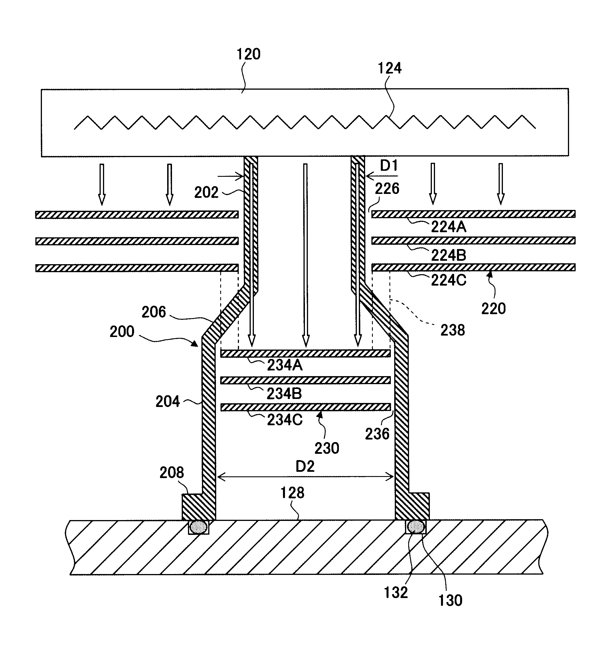
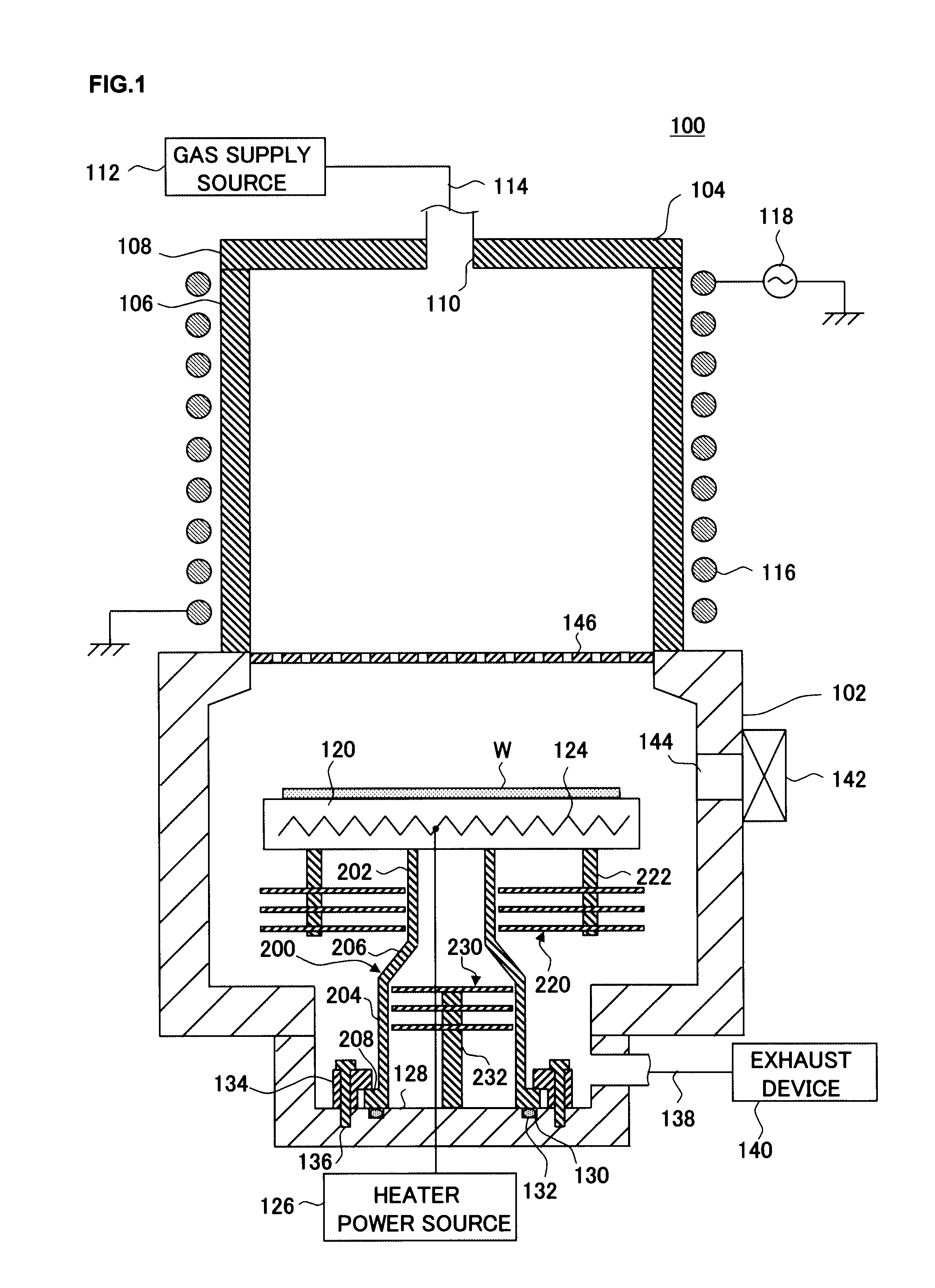
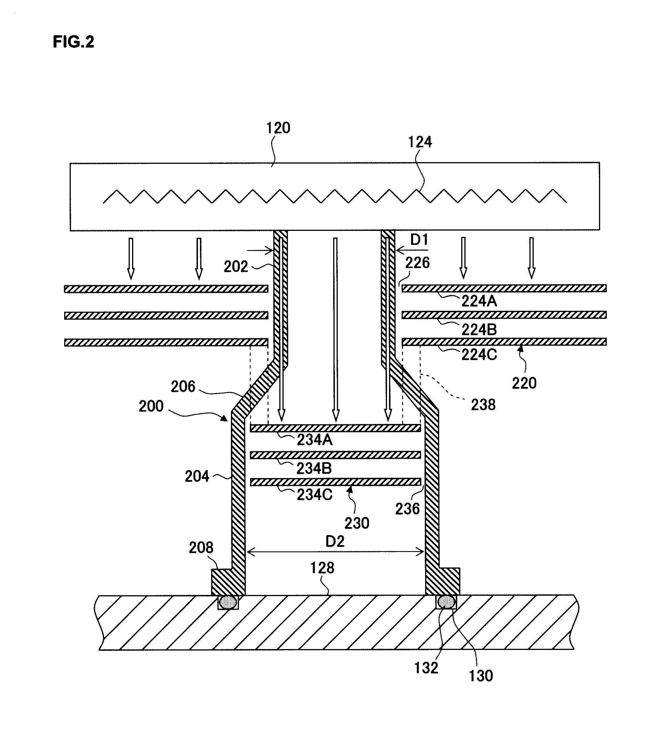
[0031]First, in reference to a drawing, a structural example that may be adopted in a substrate processing apparatus that includes the substrate stage achieved in the first embodiment of the present invention is explained. The following explanation is provided by assuming that the present invention is adopted in a down-flow type plasma processing apparatus that processes substrates by using hydrogen radicals generated from plasma (hereafter may be referred to as “hydrogen plasma”) raised from a hydrogen-containing processing gas. FIG. 1 is a longitudinal sectional view schematically illustrating the structure of a plasma processing apparatus 100 achieved in the first embodiment. In the plasma processing apparatus 100, a photoresist film formed on a low dielectric constant insulating film with a lower dielectric constant is removed through ashing by supplying hydrogen radicals over to a wafer W hav...

second embodiment

Substrate Stage Achieved in the Second Embodiment

[0070]In reference to a drawing, a structural example for the upright support at the substrate stage achieved as the second embodiment of the present invention is described. FIG. 4 is an enlarged sectional view schematically illustrating the structure of the substrate stage achieved in the second embodiment, which is similar to the enlarged sectional view presented in FIG. 2. The substrate stage in the plasma processing apparatus 100 in FIG. 1 may be replaced with the substrate stage achieved in the second embodiment. FIG. 4 shows the structures of the upright support, the outer heat shield plate and the inner heat shield plate and the positional arrangement with which they are disposed.

[0071]As shown in FIG. 4, an upright support 250 achieved in the second embodiment is constituted with a tubular member (e.g., a cylindrical member) that includes a small tube portion 252, a large tube portion 254 assuming an inner diameter D2 greater ...

third embodiment

Substrate Stage Achieved in the Third Embodiment

[0077]In reference to a drawing, a structural example for the upright support at the substrate stage achieved as the third embodiment of the present invention is described. FIG. 5 is an enlarged sectional view schematically illustrating the structure of the substrate stage achieved in the third embodiment, which is similar to the enlarged sectional view presented in FIG. 2. The substrate stage in the plasma processing apparatus 100 in FIG. 1 may be replaced with the substrate stage achieved in the third embodiment. FIG. 5 shows the structures of the upright support, the outer heat shield plate and the inner heat shield plate and the positional arrangement with which they are disposed.

[0078]While the upright support 200 in FIG. 2 and the upright support 250 in FIG. 4 are each constituted with a tubular member formed as an integrated unit that includes a small tube portion, a middle portion and a large tube portion, an upright support 26...


PUM

PropertyMeasurementUnit
temperatureaaaaaaaaaa
frequencyaaaaaaaaaa
frequencyaaaaaaaaaa

Abstract

A substrate stage includes a stage upon which a wafer is placed, a heater element installed within the stage, an upright support that ranges upright from a bottom of a processing chamber and includes a tubular member that includes a small tube portion, a large tube portion and a middle portion attached to and joins the small tube portion and the large tube portion to one another, an outer heat shield plate disposed so as to surround the outer side of the small tube portion and an inner heat shield plate. The outer heat shield plate and the inner heat shield plate are disposed so that an inner edge of the outer heat shield plate and an outer edge of the inner heat shield plate overlap along the entire circumference.

Description

CROSS-REFERENCE TO RELATED APPLICATIONS[0001]This document claims priority to Japanese Patent Application Number 2007-244462, filed on Sep. 20, 2007 and U.S. Provisional Application No. 60 / 991,826, filed on Dec. 3, 2007, the entire content of which are hereby incorporated by reference.FIELD OF THE INVENTION[0002]The present invention relates to a substrate processing apparatus that executes heat treatment on a substrate such as a semiconductor wafer or an FPD substrate or a specific type of processing such as CVD while heating the substrate, and it also relates to a substrate stage used in the substrate processing apparatus.BACKGROUND OF THE INVENTION[0003]During a semiconductor device manufacturing process, various types of gas processing such as film formation processing and etching are executed on a substrate, which may be a semiconductor wafer (hereafter simply referred to as a “wafer”). During such processing, a specific film present on the wafer may be selectively removed thro...

Claims


Application Information

Patent Timeline
Patent Type & Authority Patents(United States)
IPC IPC(8): H05B3/06H01L21/67H01L21/02F27B5/14F27B5/06H05B3/68H01L21/683H05B3/36
CPCH01L21/67109H01L21/68785
Inventor HAYASHI, DAISUKE
Owner TOKYO ELECTRON LTD
Why Eureka
Try Eureka