
Hybrid transmission method for wireless communications

a transmission method and wireless communication technology, applied in the field of hybrid transmission methods for wireless communications, can solve the problems of inefficient use of resources, large feedback delays, and inefficiency of bandwidth when transmitting shorter packets, and achieve the effects of improving bandwidth efficiency, reducing the number of packets transmitted, and finer data rate granularity

Active Publication Date: 2012-10-16
NOKIA TECHNOLOGLES OY
View PDF26 Cites 1 Cited by
  • Summary
  • Abstract
  • Description
  • Claims
  • Application Information

AI Technical Summary

Benefits of technology

The invention is a wireless communication system that uses a hybrid transmission method to improve bandwidth efficiency and reduce delays. This method involves dividing the communication channel into multiple time slots, each containing multiple sub-slots. Each sub-slot can carry a separate, simultaneous transmission, allowing for multiple simultaneous transmissions in any given time slot. This combination of time multiplexing and code multiplexing provides the benefits of both techniques while avoiding their drawbacks. The system can handle variable size packet transmissions more efficiently, resulting in improved bandwidth efficiency.

Problems solved by technology

A code-multiplexed CDMA system has several drawbacks relating to delays and memory requirements.
For example, a larger fixed frame duration is generally required in a CDMA system, which leads to larger feedback delays.
For example, there is typically bandwidth inefficiency when transmitting shorter packets because the shortest frame duration cannot be smaller than one full time slot.
Because all resources are allocated to a single user within a particular frame duration, resources are inefficiently used when a user only has a small amount of data to send due to padding or use of sub-optimal modulation and coding schemes.
Moreover, data rate granularity is coarse because frame duration can only be multiples of one slot.

Method used


Image

  • Hybrid transmission method for wireless communications
  • Hybrid transmission method for wireless communications
  • Hybrid transmission method for wireless communications

Examples


Embodiment Construction

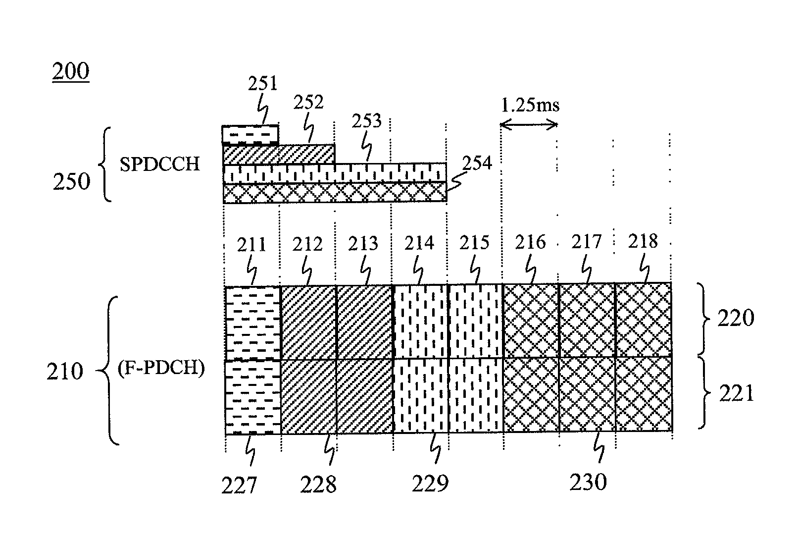
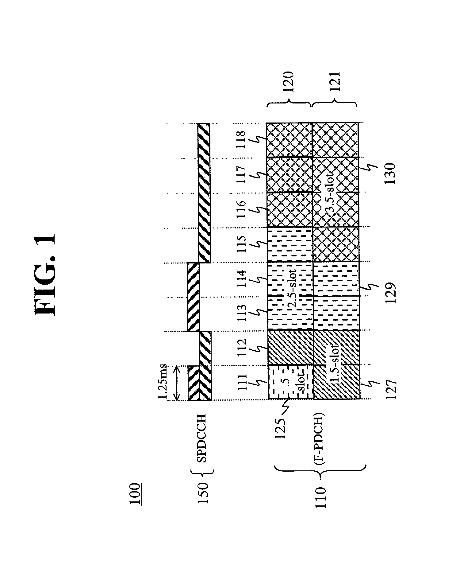
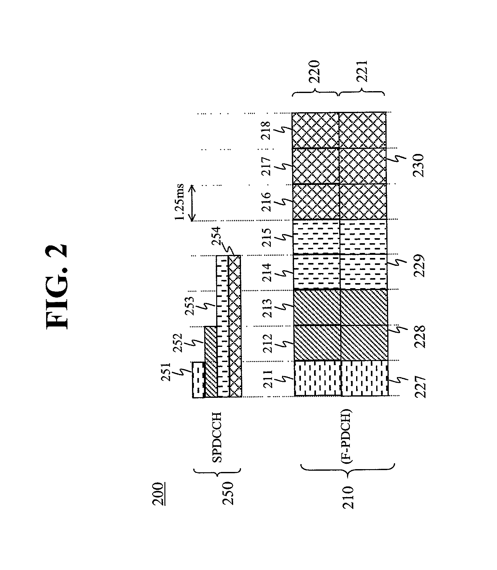
[0013]FIG. 1 shows one exemplary embodiment of the invention in the context of wireless data transmission according to the 1xEV-DV air interface standard (evolution of the cdma2000-1x standards) for third generation (3G) wireless systems. More specifically, FIG. 1 shows a simplified block diagram of a communication channel format 100 wherein a forward packet data channel (F-PDCH) 110 is used for transmitting encoder packets, according to well-known techniques, and wherein forward secondary packet data control channel (SPDCCH) 150 is used for transmitting control information associated with the data transmission in F-PDCH 110, again according to well-known techniques.

[0014]In the exemplary embodiment shown in FIG. 1, communication channel 100 is divided into eight (8) time slots 111-118 of equal duration, e.g., 1.25 milliseconds, according to the well-known cdma2000 standard. As shown, each of times slots 111-118 is further sub-divided into two (2) half-slots (sub-slots) 120 and 121....


PUM


Abstract

A method is described for transmitting information in a communication channel of a wireless communication system in which the communication channel is divided into a plurality of time slots of equal duration and each of the time slots is further sub-divided into multiple sub-slots or resource units. In one illustrative embodiment, the communication channel is divided into time slots according to a time division multiple access scheme. Each time slot is then further code-multiplexed into one or more sub-slots according to a code division multiple access scheme. Each of the sub-slots is therefore capable of carrying a separately coded transmission within the communication channel so that multiple simultaneous transmissions can occur in any given time slot.

Description

TECHNICAL FIELD[0001]The invention relates generally to wireless communication systems and, more particularly, to methods used for transmitting information in communications channels of such systems.BACKGROUND OF THE INVENTION[0002]In wireless communication systems, an air interface is used for the exchange of information between a mobile (e.g., cell phone) and a base station or other communication system equipment. The air interface typically comprises a plurality of communication channels and transmission over the communication channels can be carried out according to several well-known multiple access methods. Two such multiple access methods in wireless communications are time division multiple access (TDMA) and code division multiple access (CDMA).[0003]As is well known, CDMA-based systems employ unique codes for multiplexing separate, simultaneous transmissions over a communication channel. In a CDMA-based system, transmission duration is fixed while the users share the resour...

Claims


Application Information

Patent Timeline
Patent Type & Authority Patents(United States)
IPC IPC(8): H04J3/00H04B7/216H04B7/212H04B7/26H04J3/16H04W16/02H04W72/04
CPCH04B7/2618H04J3/1647
Inventor DAS, ARNABKHAN, FAROOQ ULLAH
Owner NOKIA TECHNOLOGLES OY
Learn More