Oil suction system

a technology of oil suction system and oil suction tube, which is applied in the direction of gearing details, machines/engines, lubrication for crankcase compression engines, etc., can solve the problems of increasing the cost of system manufacture, complicated system construction, and easy air drawing, so as to prevent air drawing. , the effect of simple construction

Active Publication Date: 2012-10-23
TOYOTA JIDOSHA KK
View PDF23 Cites 18 Cited by
  • Summary
  • Abstract
  • Description
  • Claims
  • Application Information

AI Technical Summary

Benefits of technology

[0012]The present invention provides an oil suction system that is simple in construction and prevents drawing of air.
[0014]With the above-described arrangement, even if the liquid surface of the oil is inclined in the particular direction in which the liquid level is most likely to be lowered, the inflow resistance is increased on the lowered liquid-level side of the suction port on which the liquid level is lowered, while the inflow resistance is reduced on the raised liquid-level side of the suction port on which the liquid level is raised, whereby air is less likely or unlikely to be dram into the strainer.
[0015]According to the present invention, when the liquid surface of the oil is inclined in the particular direction in which the liquid level is most likely to be lowered, the inflow resistance on the lowered liquid-level side of the suction port on which the liquid level is lowered is increased, and the inflow resistance on the raised liquid-level side of the suction port on which the liquid level is raised is reduced. It is thus possible to provide an oil suction system which is simple in construction and is able to prevent drawing of air with reliability.

Problems solved by technology

In the oil suction systems as described above, however, the oil chambers are formed by providing the mutually opposed partition walls at the interface of the cases, or the suction port is made movable in the direction of movement (shift) of the oil, thus making the construction of the system complicated and increasing the cost of manufacture of the system.
In the system in which the rear end portion of the strainer extends along the inner bottom surface of the oil pan, the suction port is located in a longitudinally middle portion of the oil pan, and the rear end portion of the strainer needs to be supported onto the oil pan, which makes the construction of the system complicated.
Furthermore, the oil suction system thus constructed cannot be expected to provide a sufficient effect of preventing drawing of air if it is employed as an oil suction system of an automatic transmission in which the depth of the oil pan is further reduced, and the strainer assumes a flattened shape extending in a horizontal plane.
Furthermore, the oil supplied to the oil pan does not evenly or uniformly flow into the suction port, because of the layout of the interior of the oil pan, and a portion having a small amount of oil appears in the oil pan.
As a result, abnormal or unusual sound due to entry of air into gears may occur in an oil pump constituted solely by a gear pump, or poor pressure regulation may occur due to entry of air into a valve body.

Method used


Image

  • Oil suction system
  • Oil suction system
  • Oil suction system

Examples


first embodiment

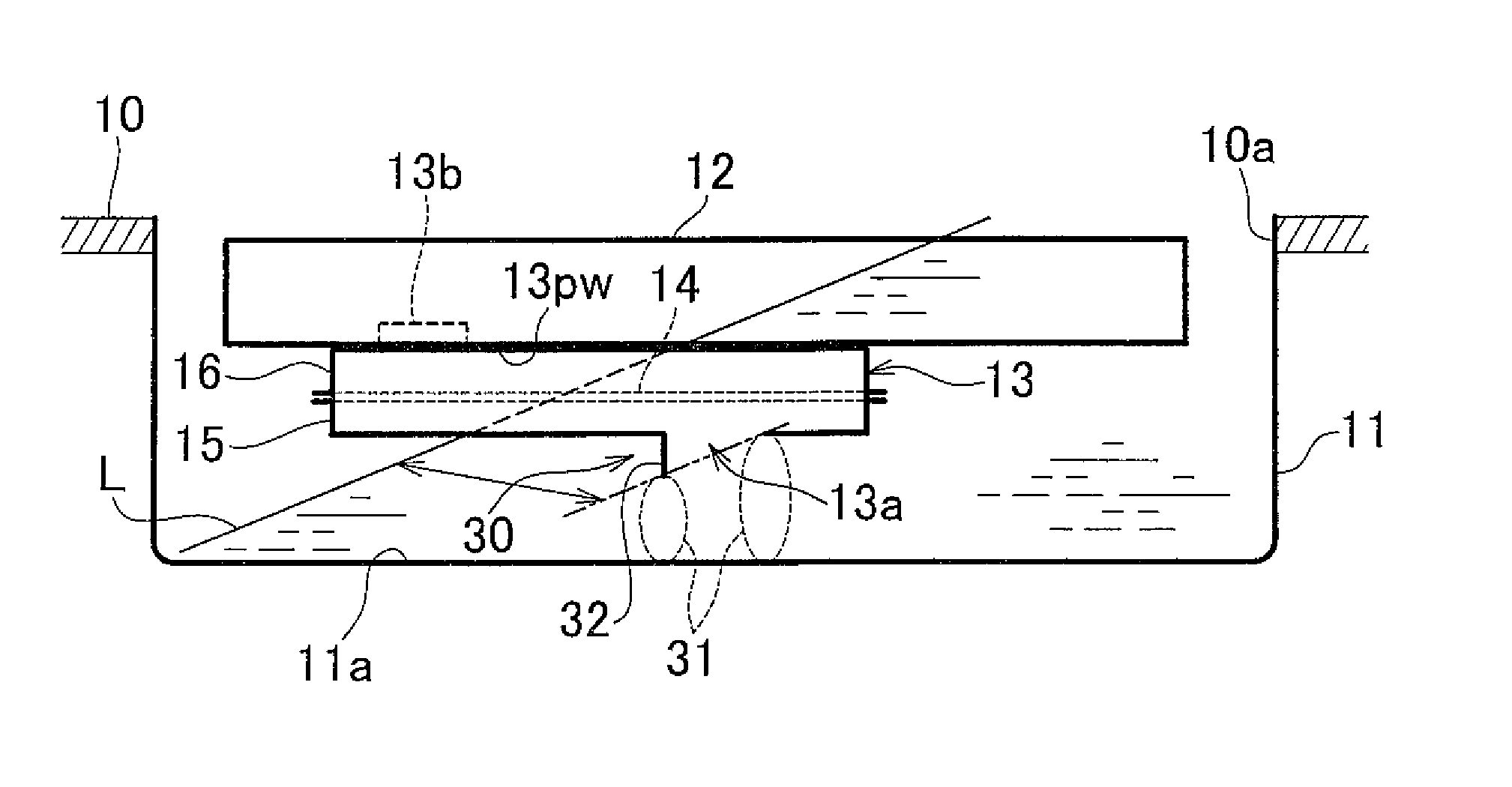
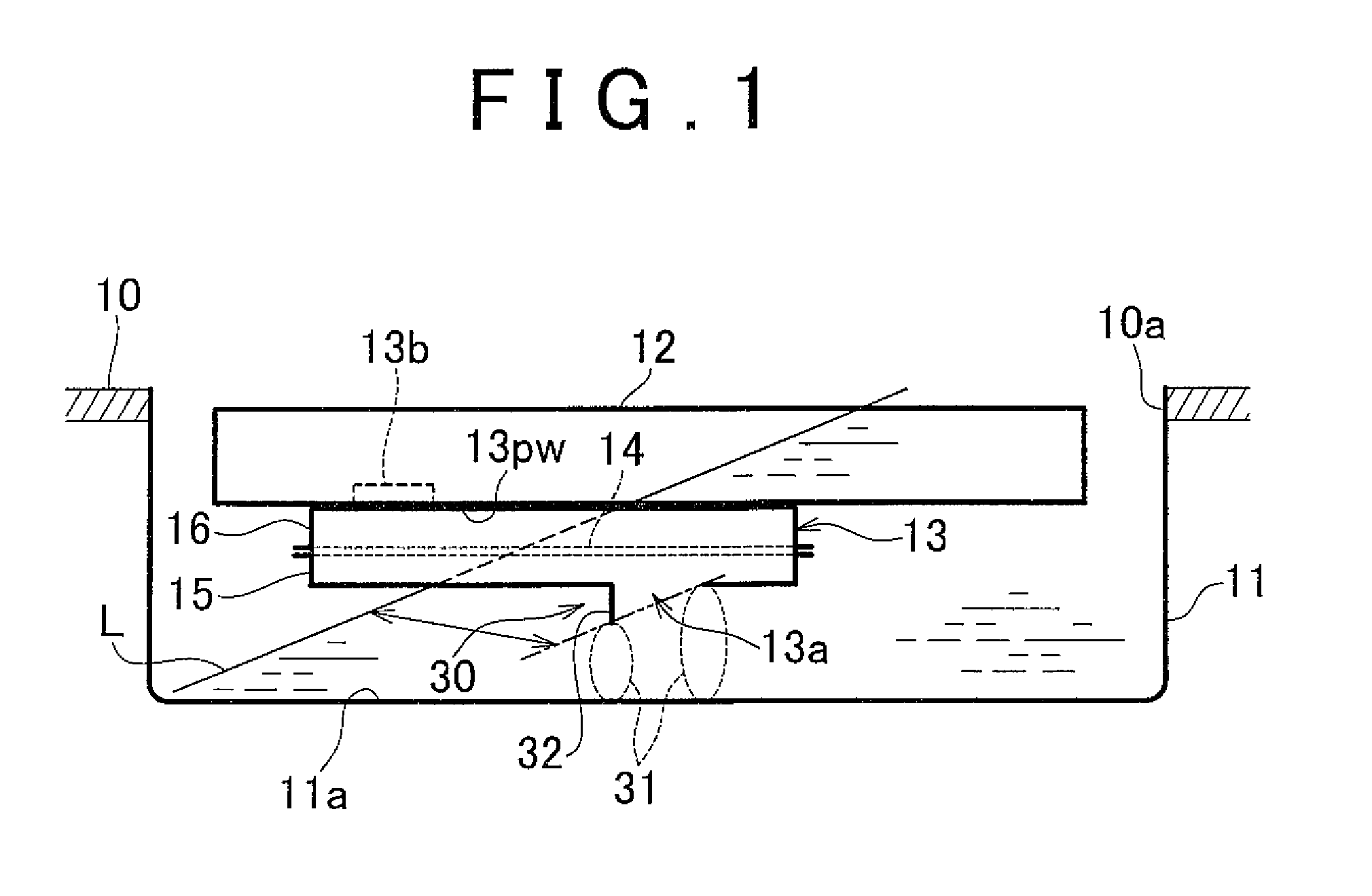
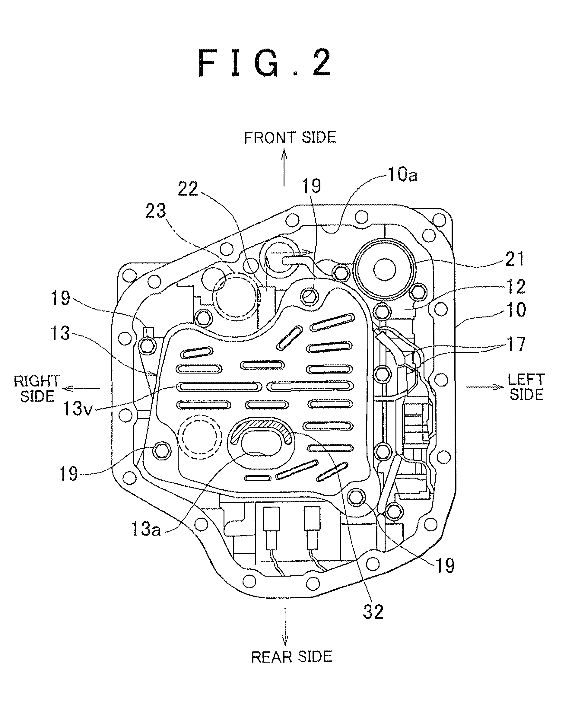
[0029]FIG. 1 is a view schematically showing the construction of an oil suction system according to the invention. FIG. 2 is a bottom view of a principal part of the oil suction system in a condition in which an oil pan of an automatic transmission (power transmitting system) on which the oil suction system is installed is removed from the system.

[0030]Initially, the construction of the oil suction system according to the first embodiment of the invention will be described.

[0031]As shown in FIG. 1 and FIG. 2, the oil suction system of this embodiment is mounted on the lower-face side of a case 10 of the automatic transmission (which will be called “transmission case 10”), and the transmission case 10 is formed with an opening 10a that receives an oil pan 11. A valve body 12 is provided in an upper part of the oil pan 11 to extend over substantially the entire area of the opening 10a, and a strainer 13 is provided under the valve body 12.

[0032]An oil pump in the form of a gear pump (...

second embodiment

[0059]In the second embodiment constructed as described above, too, when the liquid surface L of the oil is inclined in the particular direction in which the liquid level in the oil pan 11 is most likely to be lowered, the inflow resistance is increased on the lowered liquid-level side of the suction port 43a on which the amount of the oil is reduced, and the inflow resistance is reduced on the raised liquid-level side of the suction port 43a on which the amount of the oil is increased, so that air is less likely or unlikely to be drawn into the strainer 43 through the suction port 43a, and thus substantially the sane effect as that of the above-described embodiment is provided. Also, in this embodiment, the suction port 43a is located within the liquid-level assurance region A in which the level of the liquid surface L close to the suction port 43a is higher than that of the suction port 43a no matter which direction in which the liquid surface L is inclined, and therefore, drawing...

third embodiment

[0062]FIG. 5A is a side cross-sectional, view schematically showing the construction of an oil suction system according to the invention, and FIG. 5B is a view as seen in the direction of arrow B5 in FIG. 5A.

[0063]As shown in FIG. 5A, a strainer 53 of this embodiment includes a strainer member 14 as a known filter for filtering oil, and lower case 55 and upper case 56 that are opposed to each other in the vertical direction with the strainer member 14 sandwiched therebetween. The strainer member 14 and the lower and upper cases 55, 56 cooperate to form a suction passage 53pw that communicates with the interior of the valve body 12, and a suction port 53a as shown in FIG. 5B is formed in the bottom of the lower case 55 such that the suction port 53a is open in a direction that is inclined relative to the inner bottom surface 11a of the oil pan 11. Also, a connection port 53b that is connected to an oil passage that leads to the oil pump is formed in the upper case 56, and the oil tha...


PUM


Abstract

In an oil suction system for drawing up oil stored in an oil reservoir through a strainer, the oil reservoir is constructed such that, when the liquid surface of the oil is inclined due to movement of the stored oil, the level of the liquid surface close to the suction port varies in accordance with a plurality of directions of inclination of the liquid surface, and the level of the liquid surface close to the suction port is lower in a particular direction as one of the directions of inclination of the liquid surface than those in the other directions of inclination, and an inflow resistance portion is provided at a lowered liquid-level side of the suction port on which the liquid level is lowered when the oil surface is inclined in the particular direction, for increasing the resistance to flow of the oil from the lowered liquid-level side toward the suction port, to be larger than the resistance to flow of the oil from a raised liquid-level side of the suction port on which the liquid level is raised due to inclination in the particular direction, toward the suction port.

Description

INCORPORATION BY REFERENCE[0001]The disclosure of Japanese Patent Application No. 2007-275358 filed on Oct. 23, 2007 including the specification, drawings and abstract is incorporated herein by reference in its entirety.BACKGROUND OF THE INVENTION[0002]1. Field of the Invention[0003]The invention relates to an oil suction system, and in particular to an oil suction system provided in a lower part of an automatic transmission of a vehicle.[0004]2. Description of the Related Art[0005]In a vehicle, such as an automobile, including a power transmitting system, such as an automatic transmission, incorporating a hydraulic circuit, al oil suction system is installed which includes an oil pan mounted on the bottom of the power transmitting system, in order to improve the capability of collecting oil to be supplied to and discharged from the hydraulic circuit. In the oil suction system, the oil pan is often required to have a shallow depth so as to ensure a sufficient ground clearance of the...

Claims


Application Information

Patent Timeline
Patent Type & Authority Patents(United States)
IPC IPC(8): F01M11/06F16H57/02F16H57/04F16N31/00
CPCF16H57/0402F16H61/0009F16H57/0452F16H57/0443
Inventor NISHIDA, NAOFUMI
Owner TOYOTA JIDOSHA KK
Why Eureka
Try Eureka