Terahertz antenna module

a technology of antenna module and terahertz, applied in the direction of resonant antenna, optical radiation measurement, instruments, etc., can solve problems such as complex structure, and achieve the effect of simplifying structur

Active Publication Date: 2012-10-23
HAMAMATSU PHOTONICS KK
View PDF12 Cites 4 Cited by
  • Summary
  • Abstract
  • Description
  • Claims
  • Application Information

AI Technical Summary

Benefits of technology

[0008]In this terahertz antenna module, the photoconductive antenna element is fixed to the wiring board and electrically connected to the electrode of the wiring board. Further, the buffer member, the hemispherical lens, the photoconductive antenna element, and the wiring board are disposed in the recess of the container in this order from the opening side of the container, and by attaching the cover to the container, the wiring board, the photoconductive antenna element, and the hemispherical lens are pressed against the buffer member. Accordingly, transmission of electric signals to the photoconductive antenna element via the electrode of the wiring board can be realized even with a simple structure, and at least in the optical axis direction of the hemispherical lens, the hemispherical lens and the photoconductive antenna element can be properly positioned.
[0009]In the terahertz antenna module of the present invention, preferably, the recess includes a first portion on the opening side and a second portion on the cover side, and the second portion is made wider in width than the first portion as viewed from the opening side, and in the first portion, at least the buffer member is disposed, and in the second portion, at least the wiring board is disposed. Further, more preferably, the wiring board is properly positioned by the recess and the hemispherical lens is properly positioned by the buffer member so that the optical axis of the hemispherical lens passes just through the photoconductive antenna part. Accordingly, the hemispherical lens and the photoconductive antenna element can be properly positioned in the direction orthogonal to the optical axis direction of the hemispherical lens with a simple structure.
[0010]In the terahertz antenna module of the present invention, preferably, the buffer member is formed into an annular shape with an inner diameter smaller than the diameter of the spherical surface portion. Accordingly, the hemispherical lens can be reliably held and positioned while being prevented from being broken.
[0011]In the terahertz antenna module of the present invention, it is also possible that the electrode is pulled out from the surface opposite to the surface on the photoconductive antenna element side of the substrate through a via hole. Accordingly, easy access to the electrode of the wiring board can be realized.
[0013]In the terahertz antenna module of the present invention, preferably, the cover functions as a leaf spring and presses the wiring board, the photoconductive antenna element, and the hemispherical lens against the buffer member. Accordingly, the wiring board, the photoconductive antenna element, and the hemispherical lens can be reliably and easily pressed against the buffer member.Effect of the Invention

Problems solved by technology

However, in the terahertz photodetector described in Patent Document 1, for positioning the terahertz light condenser lens and the terahertz photodetection element and realizing transmission of electric signals to the terahertz photodetection element, a large number of fine components are used, so that the structure becomes complicated, which is a problem.

Method used


Image

  • Terahertz antenna module
  • Terahertz antenna module
  • Terahertz antenna module

Examples


Embodiment Construction

[0027]Hereinafter, a preferred embodiment of the present invention will be described in detail with reference to the drawings. In the respective drawings, portions identical or equivalent to each other are attached with the same reference numerals and letters, and overlapping description is omitted.

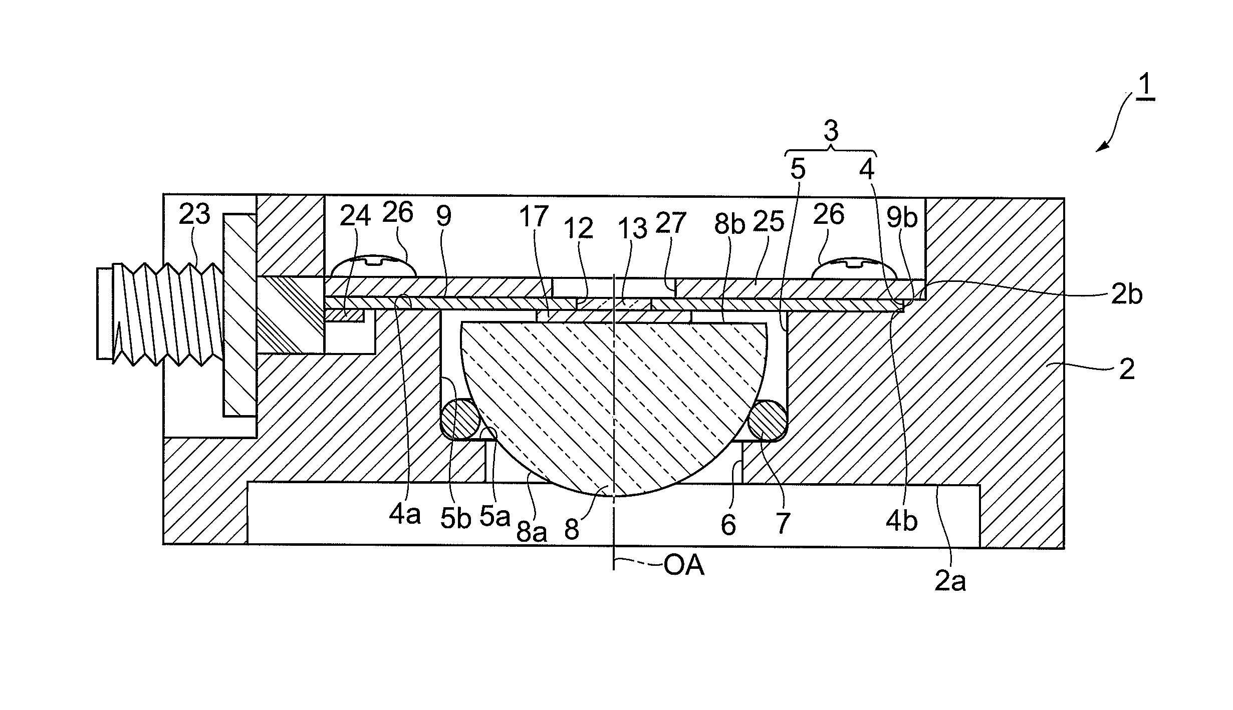
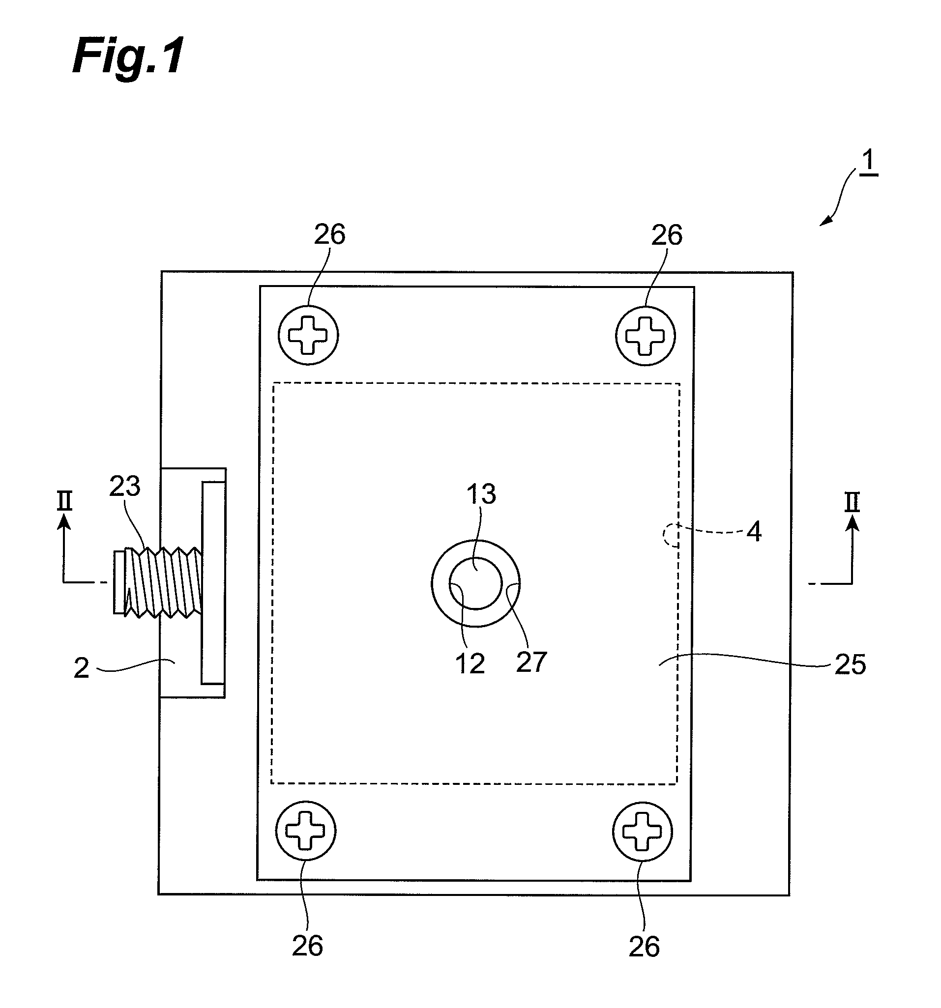
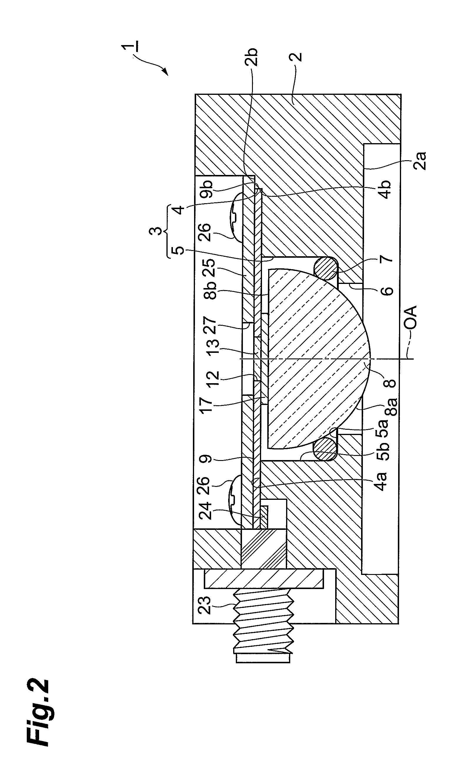
[0028]As shown in FIG. 1 and FIG. 2, the terahertz antenna module 1 generates a terahertz wave and emits it forward (downward in FIG. 2), or detects a terahertz wave made incident from the front side (lower side in

[0029]FIG. 2). The terahertz antenna module 1 includes a rectangular parallelepiped container 2 made of a metal. The container 2 may have a metal film formed on the surface of a matrix made of plastic or ceramic.

[0030]The container 2 has a recess 3 formed on the rear surface 2b. The recess 3 includes a recess (second portion) 4 having a rectangular section formed on the rear surface 2b of the container 2, and a recess (first portion) 5 having a circular section formed on the bot...


PUM


Abstract

In a terahertz antenna module 1, a photoconductive antenna element 17 is fixed to a wiring board 9, and electrically connected to an electric signal input / output pin 24 of an electric signal input / output port 23 via a signal electrode of the wiring board 9. Further, a buffer member 7, a hemispherical lens 8, a photoconductive antenna element 17, and the wiring board 9 are disposed in a recess 3 of a container 2 in this order from an opening 6 side of the container 2, and by attaching a cover 25 to the container 2, the wiring board 9, the photoconductive antenna element 17, and the hemispherical lens 8 are pressed against the buffer member 7. Further, the wiring board 9 is positioned by the recess 4 and the hemispherical lens 8 is positioned by the buffer member 7 so that the optical axis OA of the hemispherical lens 8 passes just through a photoconductive antenna part of the photoconductive antenna element 17.

Description

TECHNICAL FIELD[0001]The present invention relates to a terahertz antenna module for generating or detecting a terahertz wave.BACKGROUND ART[0002]As a conventional terahertz antenna module, for example, Patent Document 1 describes a terahertz photodetector including a terahertz light condenser lens and a terahertz photodetection element which are bonded to each other by using silicon grease, etc., and supported on a main body block. In this terahertz photodetector, the terahertz light condenser lens and the terahertz photodetection element are positioned by a main body block, a lens holding plate, and a substrate holding member, and fixed to the main body block by a pushing member in a state where a conducting member is disposed on an electrode part of the terahertz photodetection element via silver paste.[0003]Patent Document 1: Japanese Published Unexamined Patent Application No. 2004-207288DISCLOSURE OF THE INVENTIONProblem to Be Solved by the Invention[0004]However, in the terah...

Claims


Application Information

Patent Timeline
Patent Type & Authority Patents(United States)
IPC IPC(8): G01J5/08
CPCH01Q9/16H01Q9/28H01Q13/10H01Q19/062H01Q21/062H01S1/02
Inventor NAKAJIMA, KAZUTOSHI
Owner HAMAMATSU PHOTONICS KK
Why Eureka
Try Eureka