
System and method for optimizing data recovery in a parallel database

Active Publication Date: 2012-10-23
HEUER JOAN D +6
View PDF13 Cites 36 Cited by
  • Summary
  • Abstract
  • Description
  • Claims
  • Application Information

AI Technical Summary

Benefits of technology

[0013]The present invention adds logic to existing parallel database management systems such that data contained in the database logs and catalog is accessed in order to recover lost or corrupted table data without the need for roll-forward recovery. Using this data with the algorithm disclosed herein, the database manager or other such database logical entity is capable of recovering database table data to a consistent state without the need to restore from tape or other alternate restoration media. In addition, the algorithm provides decision logic such that the database manager is capable of choosing the best recovery point for the database table-space, or can display several optional recovery points for the database administrator (DBA) or user to choose from.
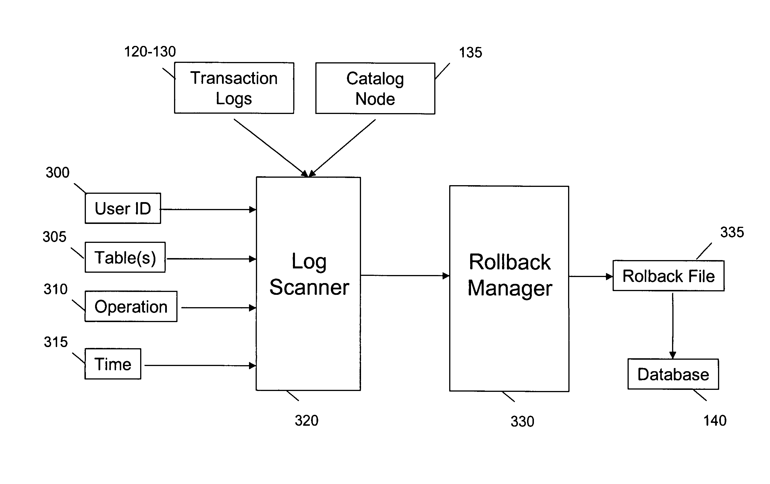
[0015]More specifically, a Log Scanner function allows the DBMS to scan individual node transaction logs, transaction catalog, back-up file history, or other necessary logs or files to determine the optimal point to which the database should be reverted, or “rolled back.” The Log Scanner allows a DBMS to perform queries over the scanned transaction logs and determine the exact operation, or query that resulted in a corruption of data. This information is then transmitted to the Rollback Manager, which allows the DBMS to perform specific tasks when recovering from data corruption or loss.
[0016]The Rollback Manager receives results from the Log Scanner and acts as an interface allowing the DBA to manage the rollback process. The Rollback Manager uses the received results to display optional and / or optimal transaction recovery points for rolling back to a specific operation or transaction that is performed on the data. The Rollback Manager also allows the DBA to rollback selected tables or selected table space in the database to a particular point of time upon command. The DBA may also use the Rollback Manager to manage the table data deletion and repopulation that takes place when a transaction within the database is rolled back.

Problems solved by technology

This allows for huge performance improvements, but also adds considerable operational complexity.
One such area of complexity is in the area of data recovery in the event that a data loss or corruption occurs.
All database systems are vulnerable to failures that can cause data loss or corruption.
Although parallel databases are becoming increasingly popular due to the amount of data that they can support and the speed at which queries can be processed, tools to manage recovery of table data in these databases are immature and insufficient.
In a typical database system, however, a more likely cause of data corruption is a user or application error.
An incorrectly formed ad-hoc query or an application software error may inappropriately delete or modify data in the database.
Traditional restore and roll-forward mechanisms are sub-optimal and inefficient for recovering data from user or application errors.
In the first place, roll-forward reconstruction requires restoring a vast amount of data.
By only rolling forward to the beginning point of the erroneous transaction, many transactions that occurred subsequent to the error, but that may have nonetheless have been valid transactions wholly independent of the specific database failure, are lost.
Although to some extent this feature mitigates the inefficiency of the roll-forward method described above, it is still not sufficiently granular to permit the selection of erroneous transactions only.
Also, since very large tables are common in data warehouses, the size of the tables may further limit the efficiency of the roll-forward procedure.
None of the prior art restore and roll-forward methods allow recovery of fine-grained objects, such as an individual row within a table.

Method used


Image

  • System and method for optimizing data recovery in a parallel database
  • System and method for optimizing data recovery in a parallel database
  • System and method for optimizing data recovery in a parallel database

Examples


Embodiment Construction

[0024]Referring now to the drawings, wherein like reference numerals designate identical or corresponding parts throughout the several views.

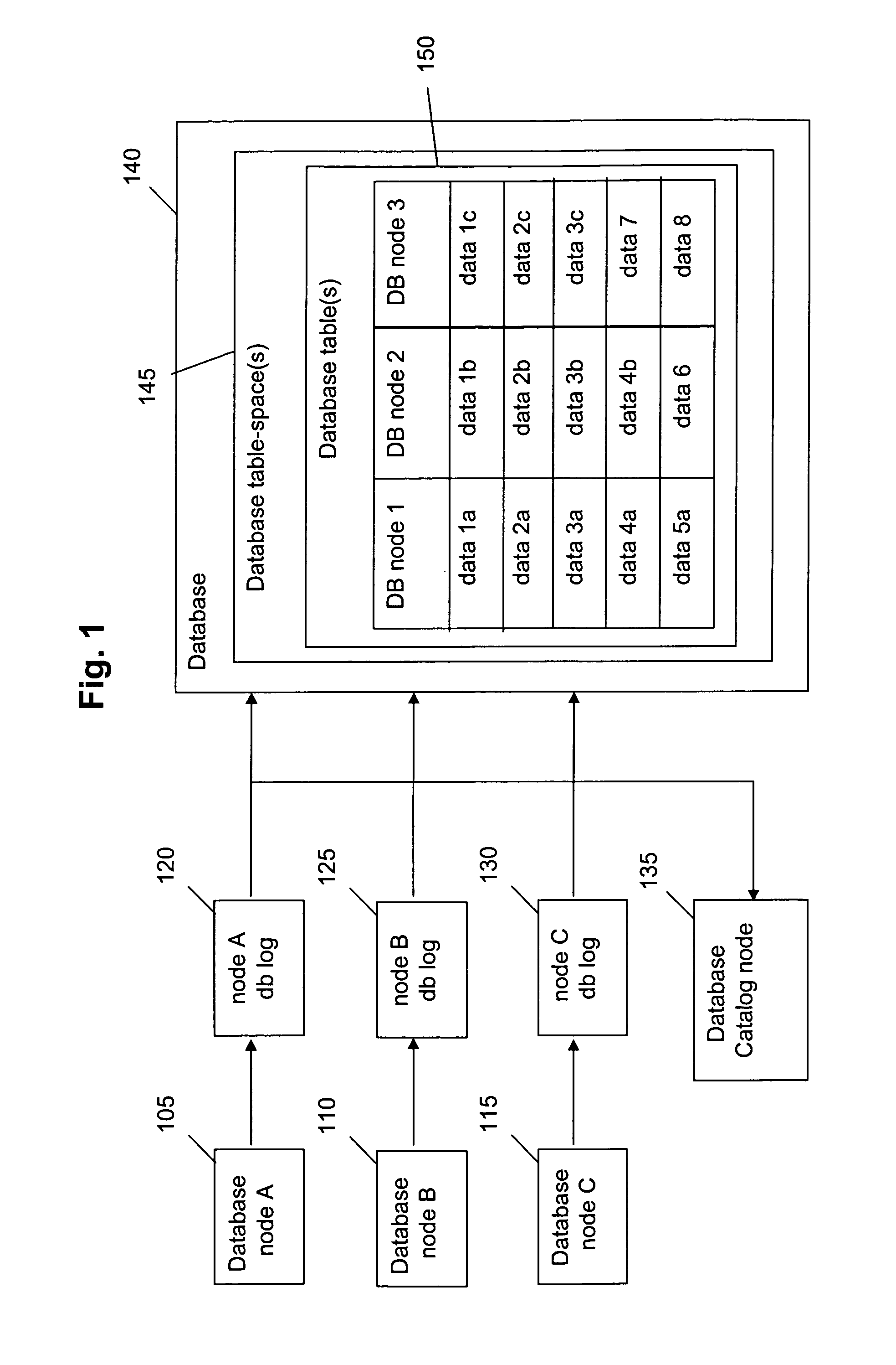
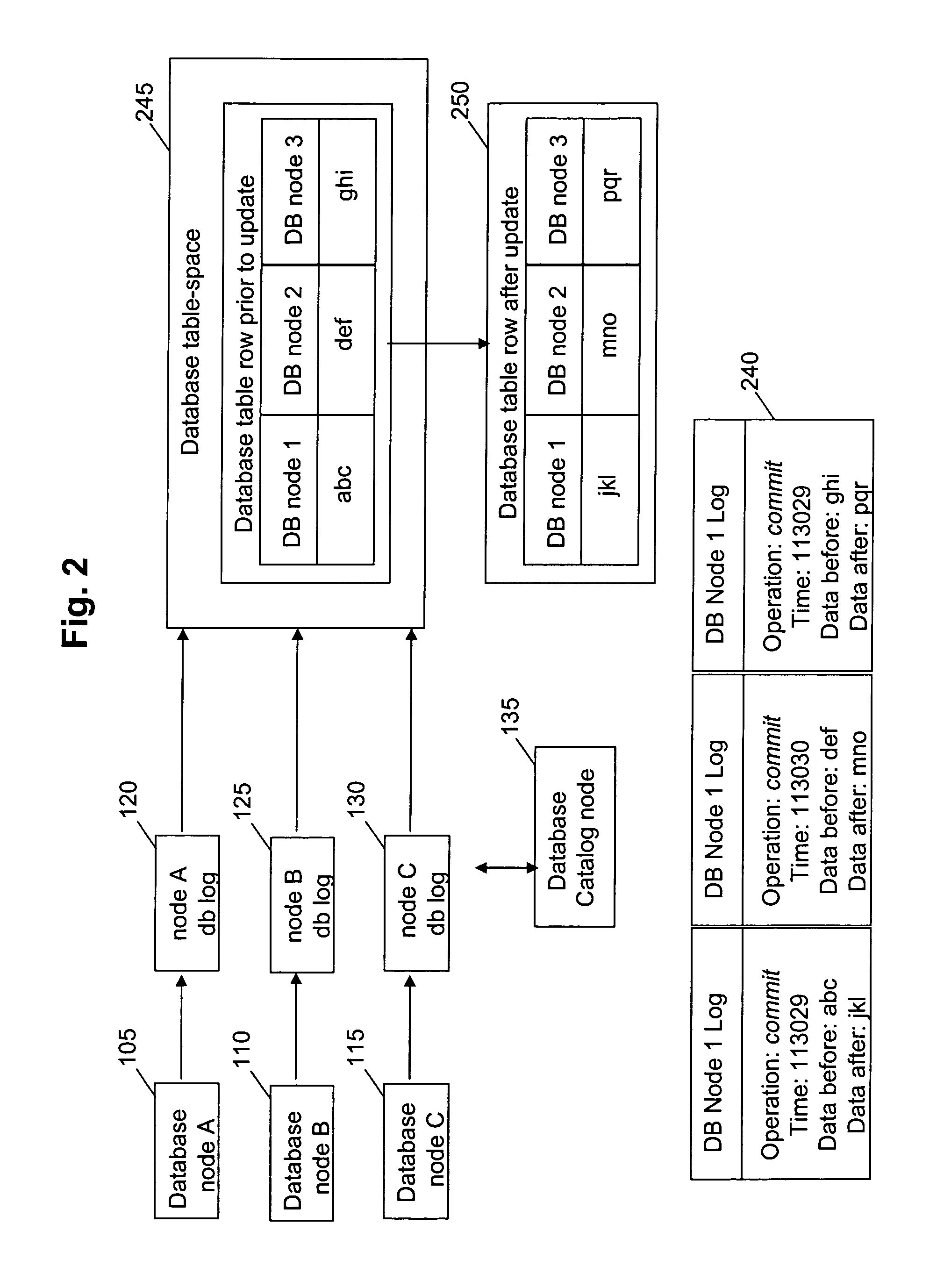
[0025]When table data becomes corrupted or lost, current embodiments of parallel DBMS systems require that the data for the affected table-space be restored to a known good point in time, typically through the manual process of restoring from a tape back-up and then rolling forward with the transaction logs to the latest consistent state. When dealing with very large tables commonly found in data warehouse environments, this can be very time consuming. Additionally, if only a subset of table-space data has been compromised or lost, it is very inefficient to restore the entire table-space. FIG. 1 depicts the basic components of a parallel database in which the present invention is implemented. A table is generally defined as a two-dimensional arrangement of rows and columns and holds data, and the context of this description includes the entiret...


PUM


Abstract

A method and system for data recovery in a parallel database system in which data stored in the database has been corrupted by a transaction or operation. Transaction log files corresponding to each node of the parallel database are scanned to determine an operation that caused the corruption of the stored data. Information corresponding to the corrupted data before the operation causing the corruption is then generated based on the scanned transaction log. The operation responsible for corrupting the data is then rolled back, and the corrupted data is replaced with the original data stored in the database prior to the corruption.

Description

BACKGROUND OF THE INVENTION[0001]1. Field of the Invention[0002]The present invention is directed to methods and computer-based systems for optimizing data recovery in a parallel database system.[0003]2. Discussion of the Background[0004]Many businesses today take advantage of relational database technology in order to store and access critical business data. Where a business stores a large quantity of disparate business data within a single database, the industry refers to such a data store as a data warehouse. Data warehousing has become very popular in that it allows a business to query data in many differing ways to learn new things with respect to customers, markets, trends, and even internal operations. Some of these large databases exist as serial entities where operations are performed between one computer (node), and one database instance (application and associated data in a single pool). The current trend, however, is for large corporate data warehouses to utilize paralle...

Claims


Application Information

Patent Timeline
IPC IPC(8): G06F17/00
CPCG06F11/1469G06F11/1471G06F2201/80G06F16/27
Inventor RICHARDSON, CRAIG PATRICKSEAMAN, JAMES WESLEYCHARBONEAU, ELIZABETH MARIE
Owner HEUER JOAN D
Learn More