Method for making wound stator of automotive generator

a technology for automotive generators and wound stators, which is applied in the direction of magnets, manufacturing tools, magnets, etc., can solve the problems of high copper loss of wound stators made by conventional winding techniques, increased overall copper loss, and inability to further enhance product performan

Inactive Publication Date: 2012-10-30
VICTORY IND CORP
View PDF8 Cites 20 Cited by
  • Summary
  • Abstract
  • Description
  • Claims
  • Application Information

AI Technical Summary

Benefits of technology

[0006]In order to overcome the aforesaid shortcomings of the prior art, it is a primary objective of the present invention to provide a novel method for making a wound stator of an automotive generator and thereby solve the efficiency problems associated with the conventional winding technique.
[0022]A stator made by the method of the present invention can effectively reduce copper loss, deliver enhanced performance, and prevent the temperature of a motor equipped with the stator from rising rapidly during operation. Besides, as the wire units are closely and neatly interlaced, the density of windings can be efficiently controlled, the slot fill factor is raised, and consequently the overall power generation efficiency of a generator using the stator is increased.

Problems solved by technology

However, a wound stator made by the conventional winding technique has high copper loss.
The overall copper loss is increased because the copper cores exposed from the wire ends of the enameled wire windings are rather long.
Hence, not only is it impossible to further enhance product performance, but also a motor equipped with such a stator is prone to temperature rise during operation.
Moreover, according to the conventional winding technique, the spacing between windings is irregular; in other words, the density of windings tends to be inconsistent.
The irregular spacing between windings also affects the slot fill factor of the enameled wires and thus lowers the overall power generation efficiency of a generator using such a stator.

Method used


Image

  • Method for making wound stator of automotive generator
  • Method for making wound stator of automotive generator
  • Method for making wound stator of automotive generator

Examples


Embodiment Construction

[0033]The characteristics, subject matter, advantages, and effects of the present invention are detailed hereinafter by reference to embodiments of the present invention and the accompanying drawings. It is understood that the drawings referred to in the following description are intended for illustrative and assisting purposes only and do not necessarily show the actual proportion and precise arrangement of the embodiments. Therefore, the proportion and arrangement shown in the drawings should not be construed as limiting or restricting the scope of the present invention.

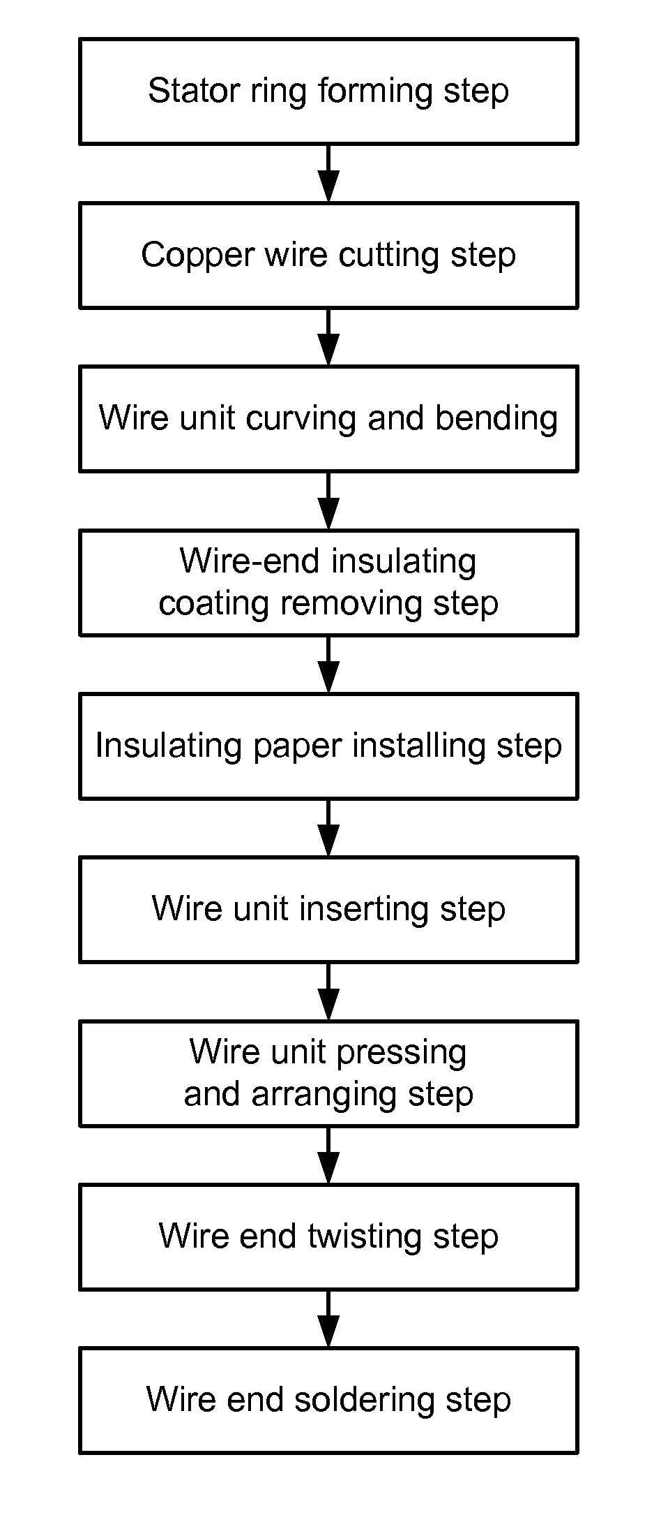
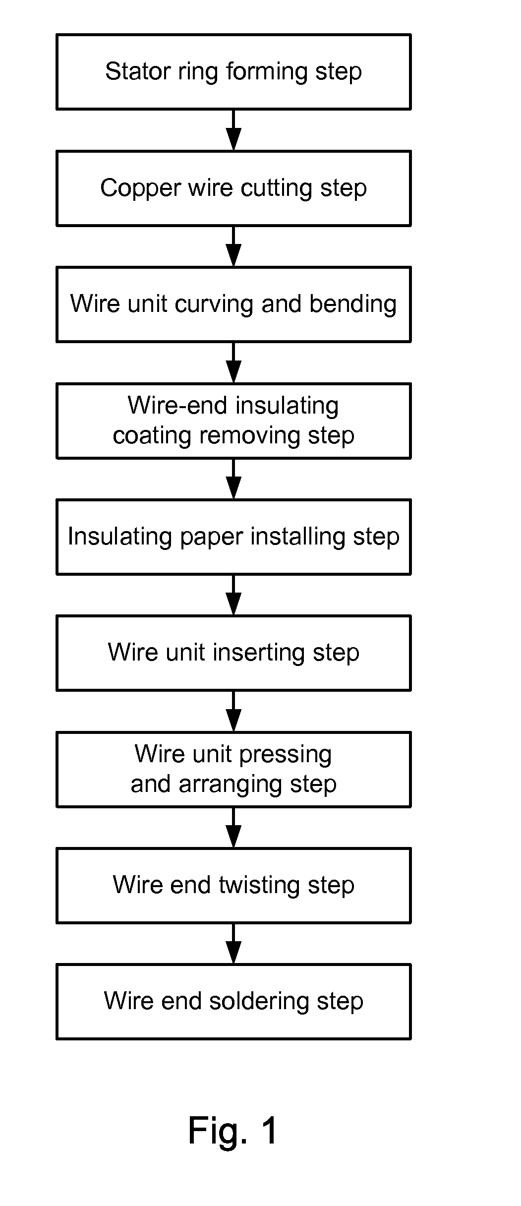
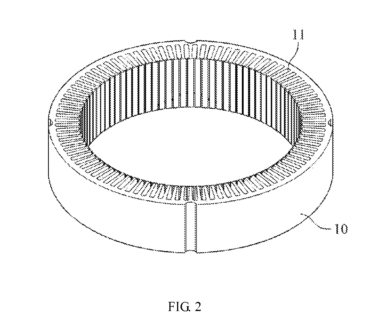
[0034]Referring to FIG. 1, a detailed method for making a wound stator of an automotive generator according to one embodiment of the present invention includes the following steps:[0035]1. Stator ring forming step,[0036]2. Copper wire cutting step,[0037]3. Wire unit curving and bending step,[0038]4. Wire-end insulating coating removing step,[0039]5. Insulating paper installing step,[0040]6. Wire unit inserting step...


PUM

PropertyMeasurementUnit
lengthaaaaaaaaaa
pressureaaaaaaaaaa
insulatingaaaaaaaaaa

Abstract

A method for making a wound stator of an automotive generator is provided for replacing the conventional winding technique. The method includes: forming a stator ring provided with a plurality of annularly arranged radial through slots; cutting a copper wire into a plurality of wire units each having a rectangular cross section; inserting the wire units into the through slots in an interlacing manner; and soldering wire ends of the wire units sequentially so as to form a connected loop.

Description

BACKGROUND[0001]1. Technical Field[0002]The present invention relates to a method for making a wound stator of an automotive generator and, more particularly, to a novel method for making a wound stator so as to enhance the power generation efficiency of a generator.[0003]2. Description of Related Art[0004]The stator is a major mechanism in an electric generator. An induced current is generated by the generator through induction between the stator and the rotor. The conventional method for making a wound stator of an automotive generator involves winding enameled wires around T-shaped claws of a stator ring so as to form a multi-layer induction coil around the stator ring.[0005]However, a wound stator made by the conventional winding technique has high copper loss. The overall copper loss is increased because the copper cores exposed from the wire ends of the enameled wire windings are rather long. Hence, not only is it impossible to further enhance product performance, but also a m...

Claims


Application Information

Patent Timeline
Patent Type & Authority Patents(United States)
IPC IPC(8): H02K15/00
CPCH02K15/0081H02K15/064Y10T29/49071Y10T29/49073Y10T29/49011Y10T29/49009Y10T29/53143
Inventor WANG, CHUN-YUANGUAN, YU-TANG
Owner VICTORY IND CORP
Why Eureka
Try Eureka